Download
1 / 165
1.75k likes | 2.01k Views
Computer Graphics and VTK. Shroeder et al. Chapter 3. University of Texas – Pan American CSCI 6361, Spring 2014. About “Libraries” and “Toolkits”. It is, of course, possible to program visual representations using just a language and its primitives for visualization

E N D
Computer Graphicsand VTK Shroeder et al. Chapter 3 University of Texas – Pan American CSCI 6361, Spring 2014
About “Libraries” and “Toolkits” • It is, of course, possible to program visual representations using just a language and its primitives for visualization • E.g., java, c/c++ and opengl (more later), for graphs, vector fields, etc. • However, many of the same visual representations are used “often”, e.g., charts scatterplots, but not often enough to be a language primitive • Libraries, or toolkits, provide a means to access these “often” used elements, focused on a domain • e.g., vtk for visualization, Qt for interface design • Such “libraries” and “toolkits” effectively another software layer • Some closer to the native language than others • Loosely stated, those “closer” to the native language are more flexible, but may trade off ease of use
“Libraries” and “Toolkits” for visualization • VTK • Allows recompilation to extend, access OpenGL, win system • Close to language, robust, established/static, many file formats supported, vis techniques oriented to “scientific” visualization • Others, http://faculty.utpa.edu/fowler/Visualization.html
“Libraries” and “Toolkits” prefuse • Toolkit in Java for building information visualizations • Fine-grained building blocks for constructing visualizations (as opposed to pre-made views) • Data model is a graph (entities & relations) • Includes library of layout algorithms, navigation and interaction techniques • Written in Java2d
“Libraries” and “Toolkits” D3 – Data-Driven Documents • Javascript-based • Very similar to Protovis… • Except use web standardse.g., Scalable Vector Graphics (SVG) vs. proprietary graphics set • Declarative Syntax like Protovis • Creating/Modifying selections of the HTML DOM • Good support for changing data • Takes advantage of CSS3 Transformations and Transitions • Integrates seamlessly into any webpage
“Libraries” and “Toolkits” D3 – Data-Driven Documents • https://github.com/mbostock/d3/wiki/Gallery, selectable examples
“Libraries” and “Toolkits” IBM’s Many Eyes • Many Eyes • IBM website • Ease of creating new visualizations • Discuss visualizations • Users upload own data sets • All become public • table or unstructured text • Word tree at right
“Libraries” and “Toolkits” Others • Piccolo • Graphics toolkit with built-in zooming and panning support • 2D • JavascriptInfoVis Toolkit • Tableau Public • Processing • Language
About Visualization • From Schroeder et al.: • The field [of visualization] is broad, including elements of computer graphics, imaging, computer science, computational geometry, numerical analysis, statistical methods, data analysis, and studies in human perception. • Tonight … • Some forest • Enough to use VTK • Some trees • Enough to “appreciate” role of cg
Computer Graphics and Visualization • Recall, 1st points in class: • (Computer-based) Visualization: • Use of computer-supported, interactive, visual representations of data to amplify cognition • Cognition is the acquisition or use of knowledge • Now, computer graphics (cg) to accomplish goals of visualization • CG – “process of generating images using computers (or rendering)” • Converting graphical data into an image • For data visualization • Transform data into “graphical data”, or graphics primitives - Points, lines, surfaces, etc. • These graphics primitives are then rendered • CG is intimately related to visualization • Sets “limits” on techniques for visualization, implicitly then creating orienting attitudes • It is part of the “craft” of visualization • Knowledge of both hardware and software systems are necessary in practice (craft) of visualization
Overview • Introduction: Software architecture of VTK and other “layers” • Photorealism and Complexity: Polygon representations • Viewing: Objects, coordinate systems, projection • Image-order and Object-order methods • Buffers: Details of graphics hardware to understand software, z-buffer algorithm • Surface properties: Shading/lighting • Cameras • Transformation matrices • VTK software architecture and an example
Software ArchitectureAbstraction and “languages” • Abstraction is at the core of computer science and information technology • Have allowed the advances seen in making electronic information systems use • E.g., advances in languages • ASM -> early “high level”, e.g., FORTRAN -> structured, Pascal, C -> object-oriented, C++, Java “Application Library” (VTK, GLUT, … or anything) Your (application) program Graphics Library (OpenGL, DirectX, …) Graphics Hardware (frame buffers, firmware, …) Window System (MS Windows, Apple, Motif) Display (and input) Hardware (screen, mouse, ….)
Software ArchitectureApplications and layers • “Libraries” essentially are higher level, or provide abstractions, for lower levels • In fact, interaction among layers • “Applications” are programs • (that programmers write) • “Libraries” and software layers have • Application programmer interfaces (APIs) “Application Library” (VTK, GLUT, … or anything) Your (application) program Graphics Library (OpenGL, DirectX, …) Graphics Hardware (frame buffers, firmware, …) Window System (MS Windows, Apple, Motif) Display (and input) Hardware (screen, mouse, ….)
Software ArchitectureInteraction among layers • VTK classes use/call: • OpenGL, which accesses Graphics Hardware • Also, Window System • And input devices, through window system • Also, application can access OpenGL and Window System • E.g., your program c/c++ or Java program, using VTK • Uses VTK classes “Application Library” (VTK, GLUT, … or anything) Your (application) program Graphics Library (OpenGL, DirectX, …) Graphics Hardware (frame buffers, firmware, …) Window System (MS Windows, Apple, Motif) Display (and input) Hardware (screen, mouse, ….)
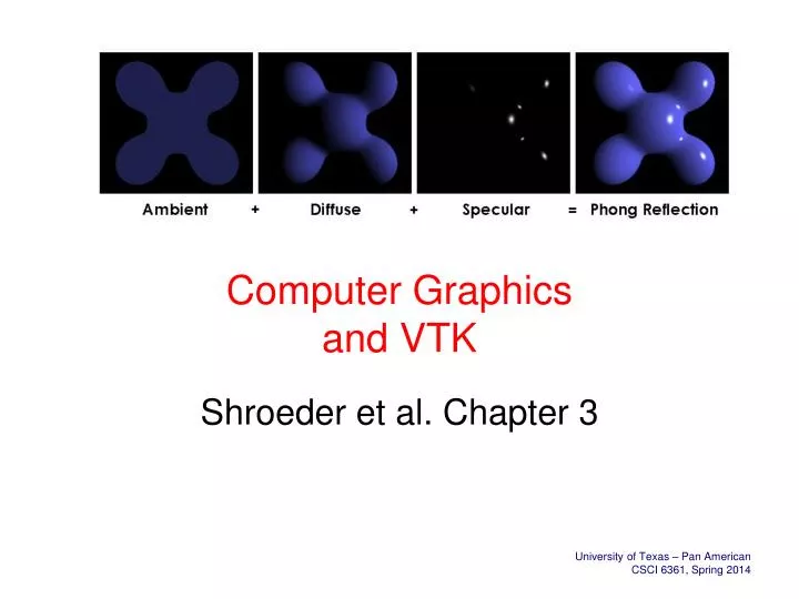
Really Big Picture - Human Vision:CG Camera model - “Light Strikes the Retina…” --- more soon • Interaction of light with human visual perceptual system leads to vision • Light strikes an object (and is reflected to our eyes) after complex series of interactions • “Photons traveling everywhere” - absorbed, reflected, refracted, diffracted, as interacts with objects • Ambient optical array is light reaching a point - Raytracing in computer graphics • View plane for computer graphics
Really Big Picture - Human Vision: CG Camera model - “Light Strikes the Retina…” --- more soon • And, of course, computer graphics, too, is about vision • “Through the view plane” • So, things about light, etc. are relevant • Physics, optics, etc. • Difference for cg is focus is on “computation”, “good (and fast) enough”, etc. • Which is at core of computer graphics • A computer science point – • Analogous to alogrithmic approximation techniques • But human vision system, task, etc. considered
CG: Photorealism and Complexity • Examples below exhibit range of “realism” in computer graphics • Realism just one of goals of computer graphics • In general, trade off realism for speed • Wireframe – just the outline • Polygons – flat shading • Polygons – smooth shading • Raytracing – consider “all” interactions of light with object Wireframe Ray tracing Polygons – Flat shading Polygons - Smooth shading
CG: Photorealism and Complexity • Examples below exhibit range of “realism” in computer graphics • Realism just one of goals of computer graphics • In general, trade off realism for speed • Wireframe – just the outline • Polygons – flat shading • Polygons – smooth shading • Raytracing – consider “all” interactions of light with object • Closest to photorealistic … but essentially follows rays from light source! Ray tracing
It’s (almost) all about Polygons • Consider tractability, interactivity and selection of image models • Not physical • Leads to using “good enough” (for the task) representation • Much of challenge of cg lies in representing the analog world on a digital device • E.g., approximation of circle as series of straight lines • Though some surfaces and objects can be described mathematically, e.g., sphere, most cannot, e.g., crocodile • Approximation for objects is typically polygon mesh Ray tracing
It’s (almost) all about PolygonsPolygons are tractable approximation • Consider tractability, interactivity and selection of image models • Not physical • Leads to using “good enough” (for the task) representation • Much of challenge of cg lies in representing the analog world on a digital device • E.g., approximation of circle as series of straight lines • Though some surfaces and objects can be described mathematically, e.g., sphere, most cannot, e.g., crocodile • Approximation for objects is typically polygon mesh Wireframe Ray tracing Polygons – Flat shading Polygons - Smooth shading
Polygon RepresentationsMore is better … for photorealism • More is always better (for polygon count and photorealism) • 20, 80, 320 for sphere • Sampling vs. discrete • Tesselation • Fair amount of detail in creating – usually tools, e.g., Maya or toolkit, e.g., VTK (below) used • vtkSphereSource *sphere = vtkSphereSource::New(); • // number of divisions of “latitude” and “longitude” • sphere->SetThetaResolution(16); • sphere->SetPhiResolution(16); • vtkPolyDataMapper *sphereMapper = vtkPolyDataMapper::New();
Polygon Mesh RepresentationsMaya example • 940 and ~1m polygons (en.9jcg.com/comm_pages/blog_content-art-51.htm) • But they are still polygons!
Representing PolygonsOpenGL Example: Draw cube from faces • VTK has similar functionality • void colorcube( ) • // vertices defined by location, etc. • { • polygon(0,3,2,1); • polygon(2,3,7,6); • polygon(0,4,7,3); • polygon(1,2,6,5); • polygon(4,5,6,7); • polygon(0,1,5,4); • } • Vertices are ordered to obtain correct outward facing normals • Many such “subtleties” in cg programming! • Normal • Direction vector, perpendicular to a surface 5 6 2 1 7 4 0 3
Representing Polygons OpenGL Example: Representing a Mesh • Consider a simple “mesh” • Already 8 nodes and 12 edges • 5 interior polygons • 6 interior (shared) edges • Each vertex has location vi = (xiyizi) • How to efficiently store for use is a significant data structure question • Hence, the large number of representations in OpenGL • … and in VTK (next slide) v5 e2 v6 e3 e9 v8 e8 v4 e1 e11 e10 v7 e4 e7 e12 v1 v3 e6 e5 v2
VTK Two-Dimensional Cell TypesMany types, fyi, in part to support formats • Triangle • Primary 2D cell type • Definition: counter-clockwise ordering of 3 points • order of the points specifies direction of surface normal • Triangle strip • Composite 2D cell consisting of a strip of triangles • Definition: ordered list of n+2 points • n is the number of triangles • Quadrilateral • Primary 2D cell type • Definition: ordered list of four points lying in a plane • constraints: convex + edges must not intersect • Polygon • Primary 2D cell type • Definition: ordered list of 3 or more points • constraint: may not self-intersect
CG Orientation: Objects, Projections, Clipping, Surfaces, View Plane
CG Orientation: Objects, Projections, Clipping, Surfaces, View Plane • Objects in a 3-D scene • Defined by whatever method • E.g., toolkit, file • Projection: Mapping 3-D to 2-D • Scene models are in 3-D space and (but) images are 2-D • so need way of projecting 3-D to 2-D • Projection: Fundamental approach: • Define a plane in 3-D space • View plane (or image plane or film plane) • Project scene onto plane • Map to window viewport • … which is all covered in cg • Determine what visible – clipping • Determine color of point on view plane • Shading
CG Orientation: Objects, Projections, Clipping, Surfaces, View Plane • Objects in a 3-D scene • Defined by whatever method • E.g., toolkit, file • Projection: Mapping 3-D to 2-D • Scene models are in 3-D space and (but) images are 2-D • so need way of projecting 3-D to 2-D • Projection: Fundamental approach: • Define a plane in 3-D space • View plane (or image plane or film plane) • Project scene onto plane • Map to window viewport • … which is all covered in cg • Determine what visible – clipping • Determine color of point on view plane • Shading
CG Orientation: Objects, Projections, Clipping, Surfaces, View Plane • Objects in a 3-D scene • Defined by whatever method • E.g., toolkit, file • Projection: Mapping 3-D to 2-D • Scene models are in 3-D space and (but) images are 2-D • so need way of projecting 3-D to 2-D • Projection: Fundamental approach: • Define a plane in 3-D space • View plane (or image plane or film plane) • Project scene onto plane • Map to window viewport • … which is all covered in cg • Determine what visible – clipping • Determine color of point on view plane • Shading
CG Orientation: Objects, Projections, Clipping, Surfaces, View Plane • Objects in a 3-D scene • Defined by whatever method • E.g., toolkit, file • Projection: Mapping 3-D to 2-D • Scene models are in 3-D space and (but) images are 2-D • so need way of projecting 3-D to 2-D • Projection: Fundamental approach: • Define a plane in 3-D space • View plane (or image plane or film plane) • Project scene onto plane • Map to window viewport • … which is all covered in cg • Determine what visible – clipping • Determine color of point on view plane • Shading
CG Orientation: Objects, Projections, Clipping, Surfaces, View Plane • Objects in a 3-D scene • Defined by whatever method • E.g., toolkit, file • Projection: Mapping 3-D to 2-D • Scene models are in 3-D space and (but) images are 2-D • so need way of projecting 3-D to 2-D • Projection: Fundamental approach: • Define a plane in 3-D space • View plane (or image plane or film plane) • Project scene onto plane • Map to window viewport • … which is all covered in cg • Determine what visible – clipping • Determine color of point on view plane • Shading
Projection: Essential Definitions(quick look) • Projectors • View plane (or film plane) • Direction of projection • Center of projection • Eye, projection reference point
Viewing, Projection, and Projectors(not a new idea) • Projection onto image plane not a new idea • Can examine evolution of artistic representations for many examples of elements to be considered in computer graphics • As perspective studied by artists, used devices to understand • Here, “projector” piece of string! “Unterweisung der Messung”, Albrecht Dürer. Woodcut 1525
CG: Classes of AlgorithmsWhat is tractable and what is not – Global and local illumination models • Again, goal of cg is to provide image on screen good and fast enough to accomplish goal • Global illumination models • Consider all light, reflections, etc. • Similar conceptually to way things work in the natural world with, e.g., the sun and the human eye • Computationally, determine image (on image plane) by going from “eye” to illumination source (bounce, etc.) • Image order/precision algorithm • Local illumination models • Consider simpler model, • Object order/precision algorithm • “Just” look at each object, determine if it will be visible and if so draw it • Surely may be millions of objects, but are cg techniques for efficiency • Clipping, visible surface determination (z-buffer), etc.
Ray TracingA global illumination image precision techniques • Image formed from all light reaching view • Ray tracing (or casting) • Basically, “running things backwards, constrained by pixels …” • Follow rays from center of projection until they either are absorbed by objects or go off to infinity • Can handle global effects • Multiple reflections • Translucent objects • Slow • Must have whole data base available at all times • Radiosity • Energy based approach • Very slow
Ray TracingA global illumination image precision techniques • High level algorithm: for each pixel on screen { determine ray from eye through pixel find closest intersection of ray with an object cast off reflected and refracted ray, recursively calculate pixel color draw pixel } • Rays cast through image pixels • Solves visibility • Complexity: • O( n . p), where n = objects, p = pixels, from above for loop or just, at each pixel consider all objects and find closest point
Ray TracingA global illumination image precision techniques • High level algorithm: • for each pixel on screen { determine ray from eye through pixel find closest intersection of ray with an object cast off reflected and refracted ray, recursively calculate pixel color draw pixel } • Recursive algorithm: raytrace( ray ) { // find closest intersection // cast shadow ray, calculate color_local color_reflect = raytrace( reflected_ray ) color_refract = raytrace( refracted_ray ) color = k1*color_local + k2*color_reflect + k3*color_refract return( color ) }
Object PrecisionLocal illumination – typically, much more tractable than global • Resolve for all possible view directions from a given eye point • Historically, first • Each polygon is clipped by projections of all other polygons in front of it • Irrespective of view direction or sampling density • Resolve visibility exactly, then sample the results • Invisible surfaces are eliminated and visible sub-polygons are created • e.g., variations on painter's algorithm, poly’s clipping poly’s, 3-D depth sort
Object PrecisionLocal illumination – typically, much more tractable than global • (very) High Level Algorithm for (each object in the world) { 1. determine parts of object whose view is unobstructed by other parts of it or any other object (visible surface determination) 2. draw pixel in appropriate color (shading) } • Complexity: • O( n2 ), where n = number of objects • from above for loop or just • “must consider all objects (visibility) interacting with all others”
Visible Surface Determination • Example of CG use of “good enough”, surface based technique to do things quickly enough for interactivity • Cleverly eliminate some surfaces for consideration • Saves time • Examples: • Painter’s algorithm • Back-face culling • (Z-buffer later – “doing it in hardware”)
Visible Surface Determination:Painter’s Algorithm • To start at the beginning … • Way to resolve visibility exactly • Create drawing order, each poly overwriting the previous ones guarantees correct visibility at any pixel resolution • Strategy is to work back to front • find a way to sort polygons by depth (z), then draw them in that order • do a rough sort of polygons by smallest (farthest) z-coordinate in each polygon • draw most distant polygon first, • Then work forward towards the viewpoint (“painters’ algorithm”) • Pretty “brute force”, but it’s easy and it works – will see z-buffer in hardware later
Back-Face Culling Example of CG technique • Back-face culling directly eliminates polygons not facing the viewer • Don’t see those • E.g., cube and house at right • And there is the constraint of convex (no “inward” facing) polygons • Computationally, can eliminate back faces by: • Line of sight calculations • Plane half-spaces • In practice can be very efficient, • surface (and vertex) normals often stored with vertex list representations • Normals used both in back face culling and illumination/shading models
Back-Face Culling: Line of Sight Interpretation • Line of Sight Interpretation • Use outward normal (ON) of polygon to test for rejection • LOS = Line of Sight, • The projector from the center of projection (COP) to any point P on the polygon. • If normal is facing in same direction as LOS, it’s a back face: • Use cross-product • if LOS . ON >= 0, then polygon is invisible—discard • if LOS .ON < 0, then polygon may be visible
Buffers • A “buffer” is just a piece-of / place-in some sort of memory • Will consider a bit, as much of pragmatics of graphics requires some elementary knowledge • And many advanced techniques that are computational tractable are available today because of commodity availability of large amounts of memory for graphics use • Moore’s law is good • Gb(s) of memory on graphics card (and gpu computing, too) • Frame buffer (and it’s depth), “scanning out an image”, double buffering, z-buffer, OpenGL Buffers