Download
1 / 82
820 likes | 828 Views
Model Translation and Cleanup. Introduction. Aim To learn how to import, check and fix models from CAD systems Why do it Vast majority of models used for analysis are imported from CAD Overview Basic steps Import CAD model Mesh model Check for errors

E N D
Introduction • Aim • To learn how to import, check and fix models from CAD systems • Why do it • Vast majority of models used for analysis are imported from CAD • Overview • Basic steps • Import CAD model • Mesh model • Check for errors • Fix mesh with Mesh Repair Wizard and manually
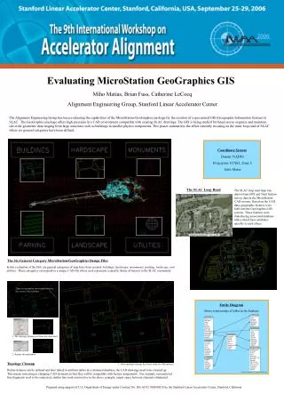
Prepare FE mesh Try 2 Prepare CAD model Import CAD model Try 1 Set mesh densities, global & local Generate mesh Evaluate mesh Initial mesh good? N Y Cleanup mesh N Fusion mesh? Y N 3D Mesh? Y Create midplane mesh Create 3D mesh End Preparing a Finite Element Mesh
In Synergy - must mesh Stereo-lithography (.stl) IGES (.igs, .iges) In MDL - must mesh STEP AP203 (.stp, step) Parasolid (.x_t, .x_b, .xmt_xmb, .xmb, .xmt) IGES (.igs, .iges) Pro-e (.prt) Catia (.catpart) Solidworks (.sldprt) In Synergy - is meshed Moldflow (.mfl) C-MOLD (.cmf) IDEAS Universal (.unv) Ansys Prep 7 (.ans) Nastran (.nas) Nastran Bulk Data (.bdf) Patran (.pat) Fem (.fem) Prepare CAD Model Parasolid, Pro-e, Catia and Solidworks need separate licenses of MDL
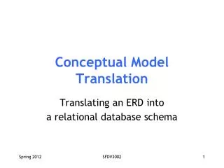
CAD System Export Options for STL • STL • Chord height • Angle control • Facet deviation • Ascii / binary C = M/(1000 x Q) where: c = chord heightp = part surfacet = tessellated surfaceM = model size (the distance between opposite diagonals of the bounding box of the part) Q = part quality (recommended 0.3, limits 0.1 to 1.0) Fine STL Coarse STL
Import a Model • Access • Import Icon • File Import • Navigate to the folder where the file is • Click on the file • Click Open
Import a Model - Geometry • Mesh type • Midplane • Fusion • 3D • If solid geometry • Pick Fusion • Cleanup model • Change mesh type as needed • Use MDL –IGES only • MDL Options
Import a Model – MDL Options • Settings • Translate surfaces • Synergy used to generate the mesh • Recommended • Generate mesh • MDL Mesh generator used • Edge Length • Auto • MDL determines • Specified • User inputs
Import a Model - STL • Mesh type • Midplane • Fusion • 3D • Pick Fusion • Cleanup model • Change mesh type as needed • Units • Change if necessary • Refer to dimensions listed
Local Mesh Sizing • Access • Mesh Define Mesh Density • Context menu (right click) • Set • On geometry • Before meshing • Change densities • Global • local • Preview
Setting Local Mesh Density • Select entities to list in dialog • Open Define Mesh Density dialog • Pick subset of entities in list by clicking on the loop • Blue lines highlight the loops • Click Apply to preview - Change as needed • Generate mesh Will Not work on STL models directly as the entire STL is considered on entity
Generate Mesh • Access • Click on mesh icon in study tasks list • Mesh Generate Mesh
Off 0.1mm 0.2mm Generate Mesh - Edge length • Global edge length • Main control of mesh density • Chord height • Controls mesh density around curved features • Use Preview button • View mesh density before meshing
Generate Mesh – Mesh Control • NURBS Surface mesher • Advancing Front • Default • Most options with this mesher • Legacy • Split-based mesher • Not as good as advancing front
Generate Mesh – Mesh Control • Surface curvature control • Puts finer mesh on curved surfaces • Proximity control • Puts finer mesh on surfaces closer together than global edge length • Chord height must be on for both No Curvature control With Curvature control No Proximity control With Proximity control
Generate Mesh – Mesh Matching • Post processing step • Ensures elements are lined up
Surface Mesh Guidelines • Not all setting are appropriate to use for Fusion meshes generally • Global edge length • Use Preview button as a guide • Fine enough to capture • Wall thickness changes • Weld lines • Other critical detail • Fusion up to several times the nominal wall • 3D up to about 2 times nominal wall
Surface Mesh Guidelines • Chord height • Default on at 0.1 • Use to capture critical circular detail • Use preview to see affect of the value • Mesh match • Off for • 3D (Fusion to be converted) • Midplane • On for Fusion • May create small sliver elements than need to be fixed
Surface Mesh Guidelines • Surface curvature control • Ensures fine mesh on curved surfaces • Proximity control • Ensures fine mesh on surfaces close together • Both controls • Chord height must be on • Primarily used for 3D models • For Fusion mesh • May be too fine • May decrease match ratio
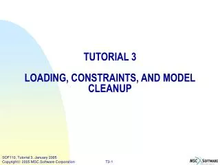
Create a 3D Mesh Set mesh type Set meshing options Generate mesh Check and fix the mesh Mesh fixed? N Y End 3D Meshing • After cleaning up Fusion mesh • Set mesh type • Right click on Fusion icon • Select Set mesh type 3D
3D Meshing • Elements through the thickness • Default 6 • Minimum 4 • 8 recommended for fiber filled • Higher to capture very fine detail • May need finer surface mesh with higher number of layers
3D Meshing • Use surface mesh optimization • Cleans up problem areas if found • Fusion mesh should be clean before converting • Use surface mesh matching • Determines placement of internal nodes by matched elements Small slivers fixed by mesh optimization Matching may need to be off on very chunky parts
None 0.5 2.0 3D Meshing • Tetra aspect ratio control • Decoupled layer optimization and aspect ratio reduction • Reduces elements and aspect ratios • Node biasing • Changes layer thicknessof elements • >1 thinner at wall • < thinner in center
3D Meshing Guidelines • Use appropriate surface mesh • Edge length ~double thickness • Clean model before conversion • Remove: Overlaps, intersections, free edges etc. • Aspect ratio before conversion • Below 30:1 • Preferred closer to 6:1 • If 3D mesh fails • Review the log file • Repair areas mentioned in the log file • Validate mesh with Mesh Repair Wizard
Create a midplane mesh Set mesh type Generate mesh Cleanup mesh End Midplane Meshing • Start with clean Fusion mesh • Set mesh type to Midplane • Generate mesh • Remeshing existing mesh • Clean mesh
Generate Mesh • Mesh now • Immediately meshes part • Job Manager • Opens Job Manager • Can send meshing to different queues
Evaluate the Mesh – Visual Inspection • Ensure mesh requirements met • Models thickness changes • Good Weld line definition To Coarse 1004 elements To Fine 58760 elements About right 8178 elements
Evaluate the Mesh – Mesh Statistics • Tool that checks and reports on the mesh quality • Entity Counts • Edge Details • Orientation Details • Intersection Details • Aspect Ratio • Match Ratio • Mesh Mesh Statistics
Mesh Mesh Diagnostics Displays specific mesh problem Aspect ratio Overlapping, intersecting elements Orientation Connectivity Free, non-manifold edges Thickness Occurrence number Zero area elements Fusion mesh match info Others for cooling Put on Diagnostics layer Used for fixing problems Restrict to visible entities Evaluate the Mesh – Mesh Diagnostics
Evaluate the Mesh – Diagnostic Navigator • Move between entities identified in the diagnostic • Automatically displayed when a diagnostic viewed • Very handy when cleaning up mesh
Evaluate the Mesh – Thickness • Fusion model thickness assigned automatically • Check for accuracy • If not correct • Could be sign of low mesh density for part • Element properties can be manually changed • Changes should not be significant
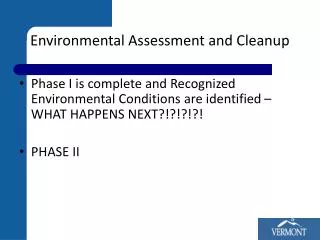
Clean up mesh Mesh repair wizard Mesh statistics, validate repair Mesh diagnostics Fix with mesh repair tools Mesh statistics N Mesh fixed? Y End Cleanup the Part • Once part is • Meshed • Evaluated • Cleanup can begin • Automatic • Manual • Verify cleanup
Cleanup the Part - Mesh Repair Wizard • Stitch free edges • Fill Hole • Overhang • Degenerate elements • Flip normals • Fix overlap • Collapsed faces • Aspect ratio
Mesh Repair Wizard – Stitch Free Edges • Merge nodes across a free edge less than specified tolerance
Mesh Repair Wizard – Fill Hole • Creates elements to fill a hole shown be free edges
Mesh Repair Wizard – Overhang • Deletes element that has one non-manifold and 2 free edges
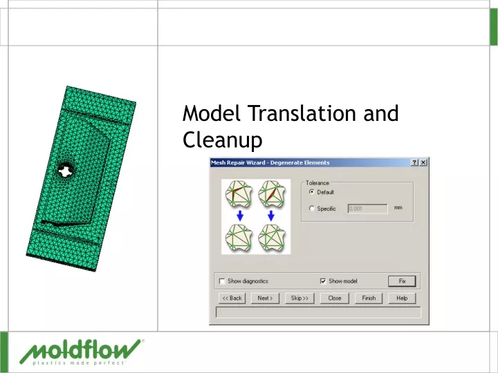
Mesh Repair Wizard – Degenerate Elements • Merges nodes or inserts then merges to fix elements below a tolerance
Mesh Repair Wizard – Flip Normals • Orients the mesh so all the elements have the correct orientation • Blue side facing outward
Mesh Repair Wizard – Fix Overlap • Attempts to correct • Intersections • Elements passing through the plane of another • Overlaps • Elements occupying the same area
Mesh Repair Wizard – Collapsed faces • Red elements are a collapsed face • Node defining the red element is also used on a opposite face
Mesh Repair Wizard – Aspect Ratio • Attempts to fix elements with an aspect ratio higher than the target
Mesh Repair Wizard -3D • Inverted elements • Collapsed elements • Mesh refinement through thickness • Edge length ratio • Volume ratio • Maximum aspect ratio • Minimum angle between tetra faces
Using the Mesh Repair Wizard • Click • Show diagnostics • Use diagnostic navigator to see problems • Tolerance • Change if necessary • Show diagnostics to see change • Click Fix or Next to correct
Validate Repairs • After using the Mesh Repair Wizard • Check the mesh • Fusion or Midplane • Mesh statistics • 3D • Run Mesh Repair Wizard again
Mesh Repair Tools • On Tools pane • In Mesh Mesh Tools menu • Tools • Create elements • Nodal mesh tools • Edge mesh tools • Global mesh tools
Mesh Repair Tools • Create elements • Create triangles • Create beams • Create tetras • Edge mesh tools • Swap edge • Stitch edge • Fill hole
Nodal mesh tools Insert Node Move Node Align Node Purge Node Match Node Merge Node Global mesh tools Remesh Area Smooth Nodes Orient Element Delete Elements Project Mesh Global Merge Auto Repair Fix Aspect Ratio Create Regions Orient Al Mesh Repair Tools
Mesh Repair Tools • Navigation • Pick tool from • Menu • Toolbox • Toolbars • Mesh manipulation • Customized • Once picked • Select from combo box • Use F2-F12 keys
Mesh Repair Tools • Entity filters • Any item • Will select any type of item or a coordinate in space • Node • Selects a node by clicking on the node or band selecting • Default for most tools • Nearest node • Selects a node by clicking on an element close to the node • Clicking directly on the node may not select • Default for some tools
Create Triangles • Creates triangles • 3 nodes selected manually • By default property of new element inherited from a neighboring element