Download
1 / 54
560 likes | 715 Views
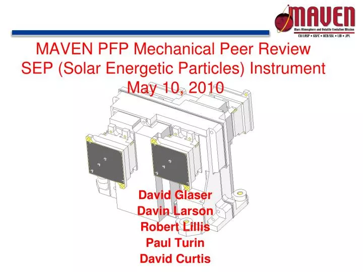
MAVEN PFP Mechanical Peer Review SEP (Solar Energetic Particles) Instrument May 10, 2010. David Glaser Davin Larson Robert Lillis Paul Turin David Curtis. Overview. Background: THEMIS SST Flight Heritage Mechanical Design Proposed Design Changes for MAVEN SEP Science Driven

E N D
MAVEN PFP Mechanical Peer ReviewSEP (Solar Energetic Particles) Instrument May 10, 2010 David Glaser Davin Larson Robert Lillis Paul Turin David Curtis
Overview • Background: THEMIS SST • Flight Heritage • Mechanical Design • Proposed Design Changes for MAVEN SEP • Science Driven • Improved Assembly • Spacecraft Driven
Background: THEMIS SST SEP will be much the same as the Solid State Telescope (SST) on THEMIS
Background: THEMIS SST Flight Heritage 10 SSTs were flown on THEMIS – 2 on each Spacecraft Mechanical design has performed well on all instruments Solid Models, drawings, and assembly procedures are well documented Most of SST design team is present Design Team Davin Larson – Lead Scientist Robert Lee – Lead Mechanical Engineer (no longer at SSL) Paul Turin – Supporting Senior Mechanical Engineer Craig Tindall (LBL) – Detector Design/Fabrication
SST Mechanical Design • SST Sensor Unit • DFE (Detector Front End) Subassembly • Magnet-Yoke Subassembly • Attenuator-Actuator Subassembly • Collimators • Support Structure • Bi-Directional FOV • Attenuator Actuation • Linear Actuators • Position Switches • Attenuator Control • Thermal Shield • Sensor Orientation on Spacecraft
Sensor Unit Schematic Foil Detector Al/Polyamide/Al Foil (stops ions <350 keV?) Thick Detector Open Detector Electrons Ions Foil Collimator Open Collimator Attenuator Attenuator Sm-Co Magnet (sweeps away electrons <350 keV) • The Solar Energetic Particle (SEP) instrument measures the energy spectrum and angular distribution of solar energetic electrons (30keV–1 MeV) and ions (30 keV-12 MeV).
Sensor Cross Section Foil Collimator Attenuator Foil Detector Stack Magnet Attenuator Open Collimator From THEMIS SST PDR
SST Mechanical Design Typical Electrical Connection Between Detector and Flex-Circuit Wirebond Loop (NOT to scale – actual loop height < 300 micron) Kapton Flex-Circuit Detector (pixelated side) From THEMIS SST CDR
SST Mechanical Design DFE Board Subassembly BeCu Gasket (3) Detectors (4) KaptonHeater Spring Clamp PEEK Spacer (4) Spring Plate (2) Kapton Flex-Circuit (4) AMPTEK Shield Thermostat Detector Board Composition (exploded view) From THEMIS SST CDR
SST Mechanical Design DFE Board Subassembly Relative Positions (2 per sensor) Detector Stack Subassembly Foil Frame Multi-Layer Circuit Board (62 mil thickness) AMPTEK Shielding Thermostat From THEMIS SST CDR
SST Mechanical Design Magnet-Yoke Assembly Co-Fe Yoke (2) Sm-Co Magnet (4) (currently not visible) Aluminum Magnet Cage From THEMIS SST CDR
SST Mechanical Design Attenuator Assembly SMA Lever (2) Attenuator (4) Cam (2) From THEMIS SST CDR
SST Mechanical Design Actuators and Position Switches Honeywell SPDT Hermetically Sealed Switch (2) SMA Actuator (2) From THEMIS SST CDR
SST Mechanical Design Two Collimators Per Side Ion Side Electron Side From THEMIS SST CDR
SST Mechanical Design Four Collimators Per Sensor Ion Side Electron Side Electron Side Ion Side From THEMIS SST CDR
SST Mechanical Design Support Structure (back section) Rigid Mounting Flange Electrical Connector Bottom Closeout Panel From THEMIS SST CDR
SST Mechanical Design Support Structure (front section) Rigid Mounting Flange Kinematic Flexure (2)
SST Mechanical Design Bi-Directional Fields-of-View From THEMIS SST CDR
Sensor Unit Mounting Using Kinematic Flexures Each sensor mounted to spacecraft panel at three points One rigid mounting flange Two mounting flanges with kinematic flexures Allows relative motion due to CTE differences between sensor structure and spacecraft panel Predicted expansion differential along instrument axes with 120 ºC temperature gradient: X-Axis: 0.006” (0.15 mm) Y-Axis: 0.013” (0.33 mm) Flexure dimensions sized to keep maximum bending stresses below 6061-T6 yield strength Factor of Safety (F.S.) > 1.4 per NASA-STD-5001 SST Mechanical Design From THEMIS SST CDR
SST Mechanical Design Attenuator Actuation – CLOSED position Honeywell Switch (compressed-position) Honeywell Switch (extended-position) SMA Actuator (retracted) SMA Actuator (extended) From THEMIS SST CDR
SST Mechanical Design Attenuator Actuation – OPEN position Honeywell Switch (extended-position) Honeywell Switch (compressed-position) SMA Actuator (extended) SMA Actuator (retracted) From THEMIS SST CDR
Attenuator Control – CLOSED to OPEN (INITIAL) SST Mechanical Design SEP Sensor PCB PCB +5V +5V CLOSE Attenuator OPEN Attenuator BACK SMA FRONT SMA (ACTIVE) NO NO GND GND FREE COMPRESSED C C SPDT Switch NC NC Monitor Monitor LOW HIGH From THEMIS SST CDR
Attenuator Control – OPEN to CLOSED (INITIAL) SST Mechanical Design SEP Sensor PCB PCB +5V +5V OPEN Attenuator CLOSE Attenuator BACK SMA (ACTIVE) FRONT SMA NO NO GND GND COMPRESSED FREE C C SPDT Switch NC NC Monitor Monitor HIGH LOW From THEMIS SST CDR
SST Mechanical Design Thermal Shielding Box was added after CDR Silver Teflon Tape
SEP Mechanical Design Sensor Orientation Relative to Spacecraft Bus
MAVEN SEP • SEP – Solar Electric Particle Instrument • Largely identical in mechanical design to SST with a few small changes • Flight heritage will allow rapid development of engineering and flight instrument models
MAVEN SEP • Mechanical Design Team • Davin Larson – Lead Scientist • Robert Lillis – Research Scientist • David Glaser – Mechanical Design • Paul Turin – PFP Mechanical Lead • Craig Tindall (LBL) – Detector Design/Fabrication
MAVEN SEP • Mechanical Work to Date • Weekly meetings since February 2010 • Compiled a list of desired improvements • Preliminary Designs of Improvements made in SolidWorks • Drivers of Design Changes • Improve science capability • Improve ease of assembly • Spacecraft Driven
SEP Design Changes from SST Increase Detector Area in Y dimension Increase Collimator FOV in Y dimension Add relief in magnet cages to reduce unwanted reflections Move detector foils closer to detectors Change foil thickness from 4.3µm to 2µm (?) Eliminate electron side attenuator (?) Blacken the attenuator paddle Reverse attenuator pinhole angle (?) Change Detector Stack Holder from PEEK to brass Change soldered detector connections to spring loaded buttons Change from one 26-pin connector to two 21-pin connectors Change Attenuator Winchester Connectors from 4-pin to 2-pin Removal of heater and thermostat from Amptek Amplifiers Survival Heaters added to housing exterior Minor changes to thermal protection box (reflect changes in allowable instrument footprint) Change Purge System Science Assembly Spacecraft
MAVEN SEP • Science Driven Changes • How can the science data be increased/improved without inducing any major design changes to the instrument? • Increase the FOV • Try to reduce scattered light reaching the detector
1. Increase Detector Size in Y Direction Design Changes from SST 7 mm 8.2 mm 13.2 mm SST Active Detector Area: 108.2 mm2 17% Larger SST Active Detector Area: 92.4 mm2
2. Increase Collimator FOV in Y Direction Design Changes from SST SEP 40° x 31° SST 40° x 23°
2. Increase Collimator FOV in Y Dimension Design Changes from SST SST FOVs were 6° and 23°, are now 11° and 31° Baffles and Collimator Apertures Enlarged in Y Dimension
2. Increase Collimator FOV in Y Direction Design Changes from SST Sunlight Reaching the Detector Nominal Sun Angle is 45° from instrument axis
3. Add Relief in Magnet Cages – to Reduce Reflections Design Changes from SST Inner Surface of Magnet Cage Can Reflect to Detector
Design Changes from SST 3. Add Relief in Magnet Cages – to Reduce Reflections Surfaces Relieved By .010 inches (Material Thickness Changed from .030” to .020”)
4. Move Foils Closer to Detectors – To lose fewer electrons to scattering Design Changes from SST Original Distance: 0.29 inches (7.4 mm) Foil Detector
4. Move Foils Closer to Detectors Design Changes from SST
4. Move Foils Closer to Detectors Design Changes from SST New Distance: 0.07 inches (~1.8 mm) New location: beneath stack holder Foil (5. Change thickness of foil (?)) Detector Stack Holder (9. Changed from PEEK to Brass) Detector Issue: Detector Vents are covered up by foil frame
6. Eliminate Electron Side Attenuators (?)-Predicted electron fluxes indicate attenuator may not be necessary Design Changes from SST
7. Blacken Attenuator Paddles 8. Reverse Angle of Attenuator Aperture (?) Design Changes from SST Current SolidWorks Model Incoming particles can reflect from sides of aperture Aperture reversed – less opportunity for reflection from sides
MAVEN SEP • Instrument Assembly Driven Changes
10. Improve Upon Soldered Detector Connections Design Changes from SST Original Design - Contacts were soldered together BeCu Spacers Kapton Flex Circuits
Design Changes from SST 10. Improve Upon Soldered Detector Connections New Design – Contacts via Spring Buttons OD .080” Gold Plated Brass Button Contacts Flex Circuit Above Gold Plated Stainless Spring – Squared End Contacts Pad on Board Spring Deflection: 0.025” Spring Force: 0.58 lb Contact Stress: ~1000 psi
Design Changes from SST 10. Improve Upon Soldered Detector Connections Flex Circuit Tabs Shortened Flex Circuits Pressed Down on Spring Buttons by an Aluminum Clamp Pads on Flex Circuits Enlarged
11. Change from one 26-pin connector to two 21-pin connectors (one for each DFE Board) Design Changes from SST SEP SST
12. Change Attenuator Winchester Connectors from 4-Pin to 2-Pin- extra pin was used for a monitor, smaller connector occupies less space Design Changes from SST 11. Change from one 26-pin connector to two 21-pin connectors (one for each DFE Board)
11. Change from one 26-pin connector to two 21-pin connectors Design Changes from SST Glenair Micro-D 21-pin Right Angle PCB Mount Connector Nut Plate (2-56 tapped holes) Each connector is mounted to its DFE board
MAVEN SEP • Changes Driven by MAVEN Spacecraft
Design Changes from SST 13. Remove Heater and Thermostat from Amptek Boxes - Because of spacecraft harnessing and also reduces noise Thermostat SST DFE Board Kapton Heater