Download
1 / 44
440 likes | 594 Views
Dr. B.Satyanarayana ▪ Scientific Officer (G) Department of High Energy Physics ▪ Tata Institute of Fundamental Research Homi Bhabha Road ▪ Colaba ▪ Mumbai ▪ 400005 ▪ INDIA T : 09987537702 ▪ E : bsn@tifr.res.in ▪ W : http://www.tifr.res.in/~bsn.

E N D
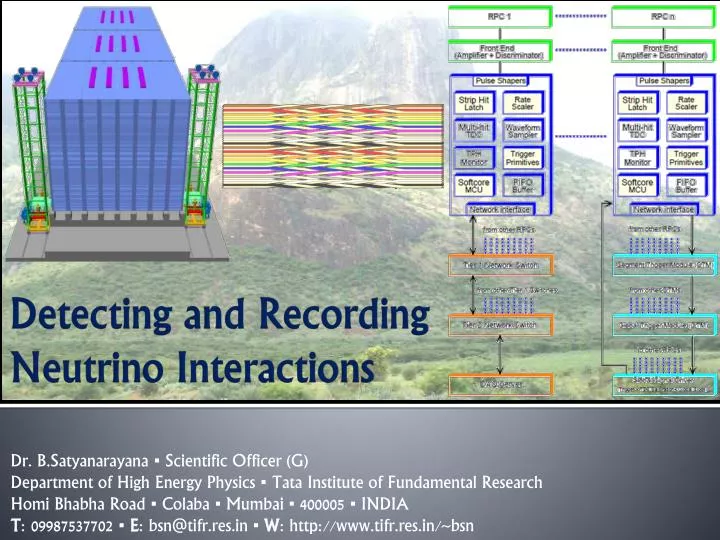
Dr. B.Satyanarayana ▪ Scientific Officer (G) Department of High Energy Physics ▪ Tata Institute of Fundamental Research Homi Bhabha Road ▪ Colaba ▪ Mumbai ▪ 400005 ▪ INDIA T: 09987537702 ▪ E: bsn@tifr.res.in ▪ W: http://www.tifr.res.in/~bsn Detecting and RecordingNeutrino Interactions
KGF Proton decay experiment Dr. B.Satyanarayana, TIFR, Mumbai Neutrinos@IISER September 16, 2013
Black and white electronics! Dr. B.Satyanarayana, TIFR, Mumbai Neutrinos@IISER September 16, 2013
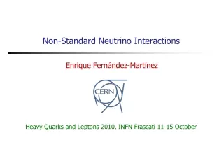
ICAL detector and numbers Magnet coils RPC handling trolleys Total weight: 50Ktons Dr. B.Satyanarayana, TIFR, Mumbai Neutrinos@IISER September 16, 2013
30 years of HEP instrumentation Dr. B.Satyanarayana, TIFR, Mumbai Neutrinos@IISER September 16, 2013
Neutrino induced interactions CC interactions NC interactions Dr. B.Satyanarayana, TIFR, Mumbai Neutrinos@IISER September 16, 2013
Iron CALorimeter detector concept Dr. B.Satyanarayana, TIFR, Mumbai Neutrinos@IISER September 16, 2013
Schematic of a basic RPC Dr. B.Satyanarayana, TIFR, Mumbai Neutrinos@IISER September 16, 2013
Signal development in an RPC • Incident radiation produces ionisation in the gas volume. Each primary electron thus produced, initiates an avalanche until it hits the electrode. • Avalanche development is characterized by two gas parameters, Townsend coefficient () and Attachment coefficient (η). • Average number of electrons produced at a distance x, n(x) = e(- η)x • Current signal induced on the electrode, i(t) = Ew • v • e0 • n(t) / Vw, where Ew / Vw = r / (2b + dr). Dr. B.Satyanarayana, TIFR, Mumbai Neutrinos@IISER September 16, 2013
Control of avalanche process • Role of RPC gases in avalanche control • Argon is the ionising gas • R134a to capture free electrons and localise avalanche e- + X X- + h (Electron attachment) X+ + e- X + h (Recombination) • Isobutane to stop photon induced streamers • SF6 for preventing streamer transitions • Growth of the avalanche is governed by dN/dx = αN • The space charge produced by the avalanche shields (at about αx = 20) the applied field and avoids exponential divergence • Townsend equation should be dN/dx = α(E)N Dr. B.Satyanarayana, TIFR, Mumbai Neutrinos@IISER September 16, 2013
Modes of operations of RPC Avalanche mode Streamer mode • Gain of the detector > 108 • Charge developed ~ 100pC • No need for a preamplier • Relatively shorter life • Typical gas mixture Fr:iB:Ar::62.8:30 • High purity of gases • Low counting rate capability • Gain of the detector << 108 • Charge developed ~1pC • Needs a preamplifier • Longer life • Typical gas mixture Fr:iB:SF6::94.5:4:0.5 • Moderate purity of gases • Higher counting rate capability Dr. B.Satyanarayana, TIFR, Mumbai Neutrinos@IISER September 16, 2013
Amplified signal of an RPC Dr. B.Satyanarayana, TIFR, Mumbai Neutrinos@IISER September 16, 2013
V-I characteristics of an RPC Glass RPCs have a distinctive and readily understandable current versus voltage relationship. Dr. B.Satyanarayana, TIFR, Mumbai Neutrinos@IISER September 16, 2013
Why ICAL chose RPC? • Large detector area coverage, thin (~10mm), small mass thickness • Flexible detector and readout geometry designs • Solution for tracking, calorimeter, muon detectors • Trigger, timing and special purpose design versions • Built from simple/common materials; low fabrication cost • Ease of construction and operation • Highly suitable for industrial production • Detector bias and signal pickup isolation • Simple signal pickup and front-end electronics; digital information acquisition • High single particle efficiency (>95%) and time resolution (~1nSec) • Particle tracking capability; 2-dimensional readout from the same chamber • Good reliability, long term stability Dr. B.Satyanarayana, TIFR, Mumbai Neutrinos@IISER September 16, 2013
Deployment of RPCs in experiments Dr. B.Satyanarayana, TIFR, Mumbai Neutrinos@IISER September 16, 2013
Materials used for RPC fabrication Schematic of an assembled gas volume Edge spacer Gas nozzle Glass spacer Dr. B.Satyanarayana, TIFR, Mumbai Neutrinos@IISER September 16, 2013
Fully assembled large area RPC 1m 1m Dr. B.Satyanarayana, TIFR, Mumbai Neutrinos@IISER September 16, 2013
RPC performance parameters Dr. B.Satyanarayana, TIFR, Mumbai Neutrinos@IISER September 16, 2013
RPC’s stability monitoring Temperature dependence on noise rate Strip noise rate profile Strip noise rate histogram Temperature Dr. B.Satyanarayana, TIFR, Mumbai Neutrinos@IISER September 16, 2013
RPC tomography using cosmic muons Dr. B.Satyanarayana, TIFR, Mumbai Neutrinos@IISER September 16, 2013
1m × 1m RPC stack at TIFR, Mumbai Dr. B.Satyanarayana, TIFR, Mumbai Neutrinos@IISER September 16, 2013
2m × 2m RPC stack at TIFR, Mumbai Dr. B.Satyanarayana, TIFR, Mumbai Neutrinos@IISER September 16, 2013
ICAL prototype at VECC, Kolkata Dr. B.Satyanarayana, TIFR, Mumbai Neutrinos@IISER September 16, 2013
Gas recirculation system Dr. B.Satyanarayana, TIFR, Mumbai Neutrinos@IISER September 16, 2013
Closed loop gas purification system Dr. B.Satyanarayana, TIFR, Mumbai Neutrinos@IISER September 16, 2013
ICAL DAQ system requirements • Information to record on trigger • Strip hit (1-bit resolution) • Timing (200ps LC) • Time-Over-Threshold • Rates • Individual strip background rates ~300Hz • Event rate ~10Hz • On-line monitor • RPC parameters (High voltage, current) • Ambient parameters (T, RH, P) • Services, supplies (Gas systems, magnet, low voltage power supplies, thresholds) Start Stop Dr. B.Satyanarayana, TIFR, Mumbai Neutrinos@IISER September 16, 2013
Challenges of ICAL electronics • Huge number of electronic data readout channels. This necessitates large scale integration and/or multiplexing of electronics. The low to moderate rates of individual channels allow this integration/multiplexing. • Large dimensions of one unit of RPC. This has bearing on the way the signals from the detector are routed to the front-end electronic units and matching the track lengths of the signals, irrespective of the geographical position of the signal source. We need to do this in order to maintain equal timing of signals from individual channels. • Large dimensions of the entire detector. This will pose constraints on the cable routing, signal driving and related considerations. • Road structure for the mounting of RPCs. This necessarily imposes constraint that signals from both X & Y planes of the RPC unit, along with other service and power supply lines are brought out only from the transverse direction of the detector. • About 40mm gap between iron layers is available for the RPC detector, out of which thickness of the RPC unit is expected to at least 24mm. Leaving another 5-6mm for various tolerances, realistically about 10mm is the available free space in the RPC slot for routing out cables etc. Dr. B.Satyanarayana, TIFR, Mumbai Neutrinos@IISER September 16, 2013
Sub-systems of ICAL instrumentation • Signal pickup and front-end electronics • Strip latch • Timing units • Background rate monitors • Front-end controller • Network interface and data network architecture • Trigger system • Event building, databases, data storage systems • Slow control and monitoring • Gas, magnet, power supplies • Ambient parameters • Safety and interlocks • Computer, back-end networking and security issues • On-line data quality monitors • Voice and video communications • Remote access protocols to detector sub-systems and data Dr. B.Satyanarayana, TIFR, Mumbai Neutrinos@IISER September 16, 2013
Overall scheme of ICAL electronics • Major elements of DAQ system • Front-end board • RPCDAQ board • Segment Trigger Module • Global Trigger Module • Global Trigger Driver • Tier1 Network Switch • Tier2 Network Switch • DAQ Server Dr. B.Satyanarayana, TIFR, Mumbai Neutrinos@IISER September 16, 2013
INO’s ASIC front-end chip • Process: AMSc35b4c3 (0.35um CMOS) • Input dynamic range:18fC – 1.36pC • Input impedance: 45Ω @350MHz • Amplifier gain: 8mV/μA • 3-dB Bandwidth: 274MHz • Rise time: 1.2ns • Comparator’s sensitivity: 2mV • LVDS drive: 4mA • Power per channel: < 20mW • Package: CLCC48(48-pin) • Chip area: 13mm2 Dr. B.Satyanarayana, TIFR, Mumbai Neutrinos@IISER September 16, 2013
RPCDAQ module – the workhorse • Unshaped, digitized, LVDS RPC signals from 128 strips (64x + 64y) • 16 analog RPC signals, each signal is a summed or multiplexed output of 8 RPC amplified signals. • Global trigger • TDC calibration signals • TCP/IP connection to backend for command and data transfer Dr. B.Satyanarayana, TIFR, Mumbai Neutrinos@IISER September 16, 2013
ICAL’s ASIC TDC chip • Principle • Two fine TDCs to measure start/stop distance to clock edge (T1, T2) • Coarse TDC to count the number of clocks between start and stop (T3) • TDC output = T3+T1-T2 • Specifications • Currently a single-hit TDC, can be adapted to multi-hit • 20 bit parallel output • Clock period, Tc = 4ns • Fine TDC interval, Tc/32 = 125ps • Fine TDC output: 5 bits • Coarse TDC interval: 215 * Tc = 131.072ms • Coarse TDC output: 15 bits CMEMS is also coming up with an ASIC with similar specs. Dr. B.Satyanarayana, TIFR, Mumbai Neutrinos@IISER September 16, 2013
Pulse shape monitor 0.2-2 ns Inverter “Domino” ring chain IN Waveform stored Out Clock Shift Register “Time stretcher” GHz MHz Dr. B.Satyanarayana, TIFR, Mumbai Neutrinos@IISER September 16, 2013
Integration challenges of front-end DAQ Front-end pre-amplifier board Dr. B.Satyanarayana, TIFR, Mumbai Neutrinos@IISER September 16, 2013
Data network schematic Dr. B.Satyanarayana, TIFR, Mumbai Neutrinos@IISER September 16, 2013
Features of ICAL trigger system • Physicist’s mind decoded! • Insitu trigger generation • Autonomous; shares data bus with readout system • Distributed architecture • For ICAL, trigger system is based only on topology of the event; no other measurement data is used • Huge bank of combinatorial circuits • Programmability is the game, FPGAs, ASICs are the players Dr. B.Satyanarayana, TIFR, Mumbai Neutrinos@IISER September 16, 2013
ICAL Trigger Scheme 367 x 400 mm boards A Ph.D. student’s work Dr. B.Satyanarayana, TIFR, Mumbai Neutrinos@IISER September 16, 2013
INO database scheme Dr. B.Satyanarayana, TIFR, Mumbai Neutrinos@IISER September 16, 2013
Software requirements • RPC-DAQ controller firmware • Backend online DAQ system • Local and remote shift consoles • Data packing and archival • Event and monitor display panels • Event data quality monitors • Slow control and monitor consoles • Database standards • Data analysis and presentation software standards • Operating System and development platforms Dr. B.Satyanarayana, TIFR, Mumbai Neutrinos@IISER September 16, 2013
Closing remarks • INO is an exciting multi-engineering project and a mega science experiment. • It is being planned on an unprecedented scale and budget. • ICAL and other experiments will produce highly competitive physics. • Beyond neutrino physics, INO is going to be an invaluable facility for many future experiments. • It provides wonderful opportunities for science and engineering students alike. • Detector and instrumentation R&D and scientific human resource development are INO’s major trust areas. • It offers a large number of engineering challenges and many spin-offs such as medical applications. Dr. B.Satyanarayana, TIFR, Mumbai Neutrinos@IISER September 16, 2013
Career opportunities in INO • Research Scholars • Applicants must have a minimum qualification of M.Sc. degree in Physics or B.E./B.Tech. degree in any one of Electronics, E & CE, Instrumentation and Electrical Engineering subjects with strong motivation for and proficiency in Physics. • The selected candidates will be enrolled as Ph.D. students of the Homi Bhabha National Institute (HBNI), a Deemed to be University, with constituent institutions that include BARC, HRI, IGCAR, IMSc, SINP and VECC. • They will take up 1 year course work at TIFR, Mumbai in both theoretical and experimental high energy physics and necessary foundation courses specially designed to train people to be good experimental physicists. • Successful candidates after the course work will be attached to Ph.D. guides at various collaborating institutions for a Ph. D. degree in Physics on the basis of their INO related work. • Career opportunities for bright engineers in Electronics, Instrumentation, Computer Science, Information technology, Civil, Mechanical and Electrical engineers Dr. B.Satyanarayana, TIFR, Mumbai Neutrinos@IISER September 16, 2013
Data sizes and rates – Event • TDC data = 1 channel for 8 strips and both the edges per hit, up to 4 hits per channel per event = 16 channels x 2 edges x 4 hits x 16 bits = 2048 bits • Hit data per RPC = 128 bits • RPC ID = 32 bits • Event ID = 32 bits • Time Stamp = 64 bits • DRS data = 16 channels x 1000 samples x 16 bits = 256000 bits • (DRS data comes in event data only if we get summed analog outputs from the preamplifier) • Data size per event per RPC • With DRS data, DR = 2048 + 128 + 32 + 32 + 64 + 256000 = 258,304 bits • Without DRS data, DR = 2048 + 128 + 32 + 32 + 64 = 2,304 bits • Considering 1Hz trigger rate, Maximum data rate per RPC = 252.25 kbps Dr. B.Satyanarayana, TIFR, Mumbai Neutrinos@IISER September 16, 2013
Data sizes and rates - Monitoring • We require to monitor 1 pick-up strip per plane per RPC. • Monitor Data per strip = 24 bits • Channel ID = 8 bits • RPC ID = 32 bits • Mon Event ID = 32 bits • Ambient Sensors’ data = 3 x 16 bits = 48 bits • Time Stamp = 64 bits • DRS data = 1000 pulses (if noise rate is 100Hz) x 16 bits x 100 samples = 1600000 bits • (DRS data comes in monitoring data only if we get multiplexed analog outputs from the preamplifier) • Data size per 10 seconds per RPC • With DRS data = 24 + 8 + 32 + 32 + 48 + 64 + 2048 + 1600000 = 1,602,256 bits • Without DRS data = 24 + 8 + 32 + 32 + 48 + 64 + 2048 = 2,256 bits • Maximum data rate with 10 second monitoring period per RPC = 156.47 kbps Dr. B.Satyanarayana, TIFR, Mumbai Neutrinos@IISER September 16, 2013