Download
1 / 5
50 likes | 166 Views
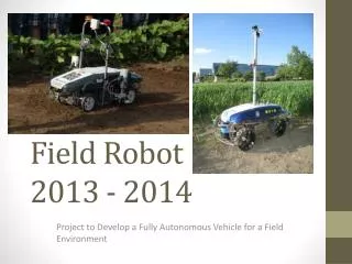
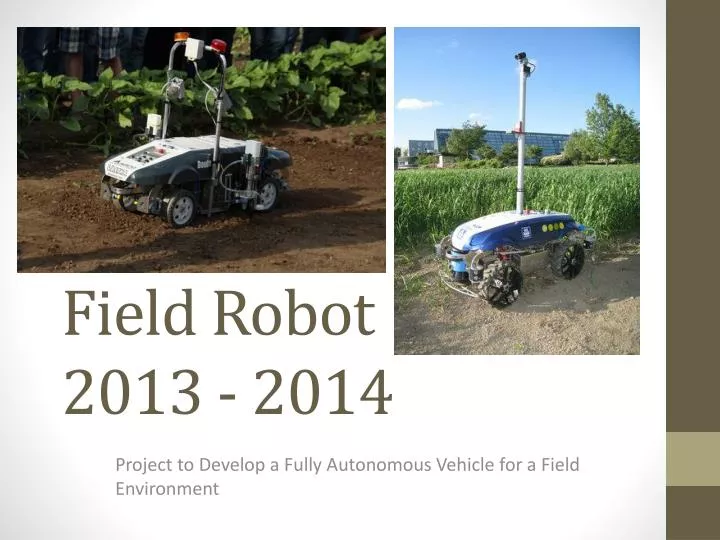
Field Robot 2013 - 2014. Project to Develop a Fully A utonomous V ehicle for a Field E nvironment. Initial plan. Automation Utilize 3D imaging with twin cameras Plant detection Enhanced Navigation Mechanical Design a new wheel module Smaller turning circle

E N D
Field Robot2013 - 2014 Project to Develop a Fully Autonomous Vehicle for a Field Environment
Initial plan • Automation • Utilize 3D imaging with twin cameras • Plant detection • Enhanced Navigation • Mechanical • Design a new wheel module • Smaller turning circle • Independent turning actuation in each wheel • Independent power output for each wheel • Higher modularity • Agri-technology • Flamethrower to eradicate weeds • Communication with separate self-attaching trailer module
Current status • Learning phase coming to an end • AS has become acquainted with Visual Studio, Windows CE and Matlab • Kinematic model has been prepared • Simulator will be done by Christmas • In January 2014 • Algorithms for positioning and navigation tested in simulator • Wheel modules will be built, chassis design started • Flamethrower arm ready for mounting, trailer design started • In February / March • Mechanical design for all components ready
Progress in Images CAD – design of the new wheel module. Casing design allows for turning up to 60 degrees. CAD – design of the flamethrower swinging arm. Final design will be able to swing left and right, lengthwise movement implemented through co-operation with the main robot using the ISOBUS standard.
Thank you • Questions?