Download
1 / 12
660 likes | 2.24k Views
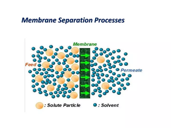
Membrane Separation Processes. Introduction. Whilst effective product separation is crucial to economic operation in the process industries, certain types of materials are inherently difficult and expensive to separate. Important examples include :

E N D
Introduction • Whilst effective product separation is crucial to economic operation in the process industries, certain types of materials are inherently difficult and expensive to separate. Important examples include: • Finely dispersed solids, especially those which are compressible, and which have a density close to that of the liquid phase, have high viscosity, or are gelatinous. • (b) Low molecular weight, non-volatile organics or pharmaceuticals and dissolved salts. • (c) Biological materials which are very sensitive to their physical and chemical environment.
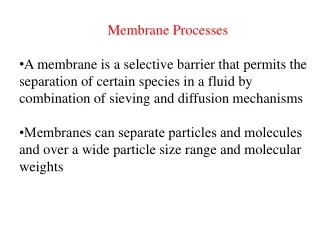
CLASSIFICATION OF MEMBRANE PROCESSES Industrial membrane processes may be classified according to the size range of materials which they are to separate and the driving force used in separation. There is always a degree of arbitrariness about such classifications, and the distinctions which are typically drawn are shown in Table 1
The nature of synthetic membranes • Membranes used for the pressure-driven separation processes, microfiltration, ultrafiltration and reverse osmosis, as well as those used for dialysis, are most commonly made of polymeric materials. Initially most such membranes were cellulosic in nature. • These are now being replaced by polyamide, polysulphone, polycarbonate and a number of other advanced polymers. These synthetic polymers have improved chemical stability and better resistance to microbial degradation. Membranes have most commonly been produced by a form of phase inversion known as immersion precipitation
MEMBRANE FOULING • A limitation to the more widespread use of membrane separation processes is membrane fouling, as would be expected in the industrial application of very finely porous materials. • Fouling results in a continuous decline in membrane permeation rate, an increased rejection of low molecular weight solutes and eventually blocking of flow channels. • Fouling is partly due to blocking or reduction in effective diameter of membrane pores, and partly due to the formation of a slowly thickening layer on the membrane surface. The extent of membrane fouling depends on the nature of the membrane used and on the properties of the process feed.
The first means of control is therefore careful choice of membrane type. Secondly, a module design which provides suitable hydrodynamic conditions for the particular application should be chosen. Process feed pretreatment is also important. • In biotechnological applications pretreatment might include prefiltration, pasteurisation to destroy bacteria, or adjustment of pH or ionic strength to prevent protein precipitation. When membrane fouling has occurred, backflushing of the membrane may substantially restore the permeation rate. This is seldom totally effective however, so that chemical cleaning is eventually required.
ELECTRODIALYSIS The principle behind electrodialysis is that electrical potential gradients will make charged molecules diffuse in a given medium at rates far greater than attainable by chemical potentials between two liquids as in conventional dialysis. When a DC electric current is transmitted through a saline solution, the cations migrate toward the negative terminal, or cathode, and the anions toward the positive terminal, the anode. By adjusting the potential between the terminals or plates, the electric current and, therefore, the flow of ions transported between the plates can be varied. Electrodialysis can be applied to the continuous-flow type of operation needed in industry. Multi-membrane stacks can be built by alternately spacing anionic- and cationic-selective membranes.
problems associated with the electrodialysis process, concentration polarization is perhaps the most serious (Concentration-polarization is a problem which also exists in reverse osmosis systems, and is due to of a build-up in the concentration of ions on one side of the membrane and a decrease in concentration on the opposite side. This adversely affects the operation of membranes and can even damage or destroy them.). Other problems in practical applications include membrane scaling by inorganics in feed solutions as well as membrane fouling by organics.
Principal applications of electrodialysis include(1)Recovery of materials from liquid effluents, such as processes related to conservation, cleanup, concentration, and separation of desirable fractions from undesirable ones; (2) Purification of water sources; (3)Effluent water renovation for reuse or to meet point source disposal standards required to maintain suitable water quality in the receptor streams. Added control of the movement of the ions can be obtained by placing sheet-type membranes of cation- or anion-exchange material between the outer plates, as shown diagrammatically in Figure 1. These sheets of cationselective resins and anion-selective resins permit the passage of the respective ions in the solution. Under an applied DC field, the cations and anions will collect on one side of each membrane through which they are transported and vacate the other side.
Another kind of electrodialysis cell configuration, shown in Figure 4, is a multiple electrodialysis system consisting of ten-unit cells, in series rather than manifolded in parallel. The feed solution is introduced at four points: It enters at both upper end points to sweep directly through both electrode chambers and is introduced into the working chambers near either end. The feed solution into the left side traverses depleted chambers and exits as depleted effluent at the right. The feed solution into the rightmost enriching cell flows in the other direction and exits as enriched effluent at the left side.
Current efficiency can be calculated from the following formula: