Download
1 / 15
150 likes | 165 Views
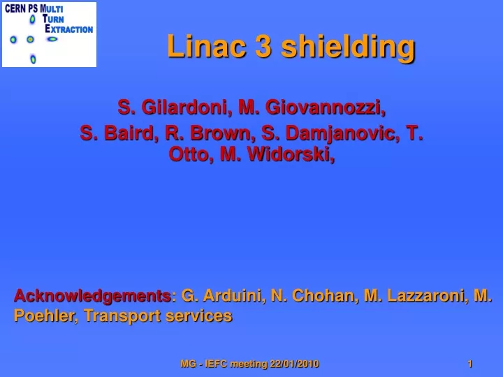
Linac 3 shielding. S. Gilardoni, M. Giovannozzi, S. Baird, R. Brown, S. Damjanovic , T. Otto, M. Widorski,. Acknowledgements : G. Arduini, N. Chohan, M . Lazzaroni , M. Poehler , Transport services. MTE losses at extraction.

E N D
Linac 3 shielding S. Gilardoni, M. Giovannozzi, S. Baird, R. Brown, S. Damjanovic, T. Otto, M. Widorski, Acknowledgements: G. Arduini, N. Chohan, M. Lazzaroni, M. Poehler, Transport services MG - IEFC meeting 22/01/2010
MTE losses at extraction Losses at extraction, about 2-3% ofcirculating beam, concentrated in 2 points.Losses at septum 16 due to kicker risetime (~ 350 ns) and the longitudinal structure required by the SPS (de-bunched beam). Issue anticipated in the MTE Design Report. HW solution: design a thinner septum. MG - IEFC meeting 22/01/2010
Linac3 issue • Due to the (weak) existing shielding, the dose in the Linac3 tunnel would exceed the current area classification during MTE operation with 0.85×10¹³ p/s (typical CNGS operation). • This results is based on a series of measurements performed on November 9 2009. • The dose will be about 13 mSv/h using MTE, whereas the limit is 10 mSv/h. • With the CNGS based on the CT extraction it was measured about 4 mSv/h. • NB: access to the Linac3 is required for continuous tuning of the Lead source and in particular during the next run for the commissioning of the new source MG - IEFC meeting 22/01/2010
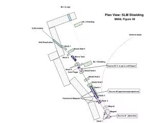
The area TT2 PS SMH16 Linac3 LEIR MG - IEFC meeting 22/01/2010
Existing radiation monitors MG - IEFC meeting 22/01/2010
Shielding foreseen during LEAR construction During LEAR construction, to accommodate injection/extraction line about 2 m of earth shielding removed. Reinforcement of remaining shielding proposed but not realised. MG - IEFC meeting 22/01/2010
PS Septum 16 zone MG - IEFC meeting 22/01/2010
LEIR injection/extraction tunnel MG - IEFC meeting 22/01/2010
Possible solutions for this year • Install shielding wall in the LEIR injection/extraction tunnel • Presence of small service tunnel for water at ceiling level. Tunnel cannot be shielded, shielding efficiency of the wall reduced. • Gallery passage reduced. Impossible to change a magnet in case of failure without removing the shielding (about 10 days). • Cables on cable tray near the ceiling are already reaching a high temperature: a shielding wall will prevent air circulation. • No impact on PS tunnel infrastructure. • Install wall shielding in the PS nearby the zone of the septum 16 • Heavy charge on the floor: impact on structural stability to be verified. • No impact on repairing activities in the area (septum 16, QFO105). • High shielding efficiency. Solution discarded MG - IEFC meeting 22/01/2010
Details of the installation Wall about 11 m long parallel to the existing tunnel wall. Thickness 80 cm. Material either Iron or Concrete. MG - IEFC meeting 22/01/2010
Fluka simulations to estimate wall shielding efficiency MG - IEFC meeting 22/01/2010
Possible wall material for this year • Iron wall (weight ~ 150 t, 11 m long, 80 cm thick, 2.4 m height) • Predicted dose reduction factor 20 (needed < 2) • No time for installation (painting required plus 3-4 days installation) with current accelerator schedule • Less ALARA, i.e. more dose to transport during installation/eventual removal for interventions in the zone • Concrete wall (weight ~ 50 t, 11 m long, 80 cm thick, 2.4 m height) • Predicted dose reduction factor 4-5 (needed < 2) • Compatible with current accelerator schedule • Faster installation/removal • Material available • Both walls are compatible with the available floor space and floor strength after the reinforcement of the small pillars under the floor and the exchange of concrete floor plates with iron plates -> activities already ongoing Solution discarded MG - IEFC meeting 22/01/2010
Wall implementation MG - IEFC meeting 22/01/2010
Conclusions • Linac3 radiation levels turned out to increase due to the MTE losses concentrated at the septum 16. During CNGS operation with exclusively CT extraction larger doses than past years observed. The problem was generated by the choice of not consolidating the shielding between the PS and the LEAR injection/extraction line during the LEAR construction. • A concrete wall will be installed before the restart of the machine as compensatory measure. • In case the shielding would turn out to be not sufficient for reasons unknown at the moment, CNGS could be delivered during the day (work ongoing in Linac3) with CT extraction, and during the night with MTE. • The installation of the wall should be considered as a temporary solution. The current run should be used to look for a better one, for example: • Revise the current installation of the Linac3 equipments (radiation mapping of the Linac3 area needed -> detailed measurements to be performed this year) • Install shielding on the Linac3 side (if possible) • Change the extraction septum (longer time scale) • … etc… • Hopefully the use of MTE in normal operation should also bring a better extraction efficiency thanks to optimisation. MG - IEFC meeting 22/01/2010