Download
1 / 40
530 likes | 1.21k Views
GRADUATION PROJECT Foundation System Design for Al Nimmer Commercial Building Prepared by: Noor S.Issa Hala S.Qasem Heba A.Massri Iman Abu Durrah. To provide some background information about foundation systems.

E N D
GRADUATION PROJECT • Foundation System Design for Al Nimmer Commercial Building • Prepared by: Noor S.Issa • Hala S.Qasem • Heba A.Massri • Iman Abu Durrah
To provide some background information about foundation systems. To design piles foundation system for the proposed building. To design Mat over Piles as an alternative foundation system. To make cost & duration estimation for both systems. Project Objectives
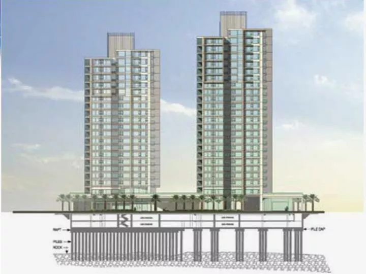
BuildingDescription • The plan area = 405m ². • Number of floors =13 floors such that: • Two basement floors (3.5 m height). • One ground floor and ten replicated stories (3 m). • Located at the city center of Nablus.
Introduction The main purpose of foundation is to receive structural loads and external loads applied to the structure and transmit them in to the soil at a given depth below the ground safely (without causing soil failure or unsafe differential settlement of the supported structure).
General Requirements of Foundations • Depth must be adequate and below the zone of seasonal volume changes. • System must be safe against overturning, rotation, sliding, and soil rupture. • The foundation should be economical.
Review of Foundation Types Shallow Foundations: • Isolated (Spread) Foundations. • Combined Foundation. • Continuous(Wall) Foundation. • Strip Foundation. • Mat Foundation.
Review of Foundation Types • Deep Foundations: • Piles. • piers. • Caissons.
Piles piles are long members that transfer the load to deeper soil or rock of high bearing capacity avoiding shallow soil of low bearing capacity, and they can be precast or cast in situ.
Piles • Classification of piles with respect to load transmission: • End bearing piles. • Skin friction piles (cohesion piles). • Combination of friction and end bearing piles.
Structural Analysis A structural analysis has been done for the proposed building using the software program SAP in order to determine the superstructure loads acting on the foundation level, and the readings were very close to the manual measurements when comparing them.
Results of Structural Analysis Allowable loads of columns at the foundation level.
Results of Structural Analysis Load of building : Manually: building load =101118.5 KN. From SAP: building load =99171.87 KN. Error = 1.96% < 5%.
Subsurface Exploration • Three boreholes were dug out, one is 20 m depth and two are 12 m depth according to the standards, from these boreholes the main soil type is sedimentary dark brownish silty clay of high plasticity with pebbles. • Lab tests has been conducted on soil samples from the boreholes at different depths, these tests included moisture content, atterberg limits, and undrained cohesion.
Recommendations • Piles Foundation is recommended for this site. • Excavation support system should be constructed for this project (about 8 m below the existing ground surface).
Piles Foundation Design • Types and Capacity of Piles: AllPiles program was used to determine the allowable bearing capacity for some common types of piles each has a specific diameter and length.
Types of Piles Used The two main types of piles that found to be the most suitable to be used for this loading system are mentioned in the table below.
Foundation Design Foundation design includes: • Design of piles and caps under columns. • Design of piles and caps under shear walls. • Design of tie beams between pile’s caps.
Critical Columns • Columns were divided into groups, each has a representative column (the critical one) as in the following table.
Design Calculations For every critical column the calculations are: • Number of piles needed under column. • Cap dimensions and piles distribution. • Depth of cap (according to one way shear). • Checking punching for both column and piles. • Steel reinforcement for both piles and piles cap.
Design Theories • No. of piles under column= • Minimum center to center spacing =2.5diam between adjacent piles. • 20 cm minimum clear distance between the edges of cap and pile, that acts as a cover for the pile.
Design Theories • Depth of cap according to one way shear: Vu.pile = ФVc = • Punching check: • If Bc ≤ 2; • If Bc > 2;
Design Theories • Main Reinforcement: As =ρ b d. • Minimum Reinforcement: Asmin= .0018 bh.
Piles Reinforcement (Theory) • Vertical Reinforcement: • Pile capacity =ФPn >Vu.pile As.pile = 0.5% Ag. • ФPn = 0.7x0.85x [(0.85xƒc x (Ag – As) + (As fy)]. • Spiral Reinforcement: • Assume bars diameter (12 mm). • Find spacing between spirals from the equation:
Design of Shear Walls • No. of piles under shear wall= • Shear wall No.1 8 piles. • Shear wall No.2 3 piles. • Minimum center to center spacing = 2.5diam.
Design of Shear Walls • Piles reactions are at the center of shear wall so: • Effective depth of cap “d” =30 cm (minimum), and total depth “h”= 45 cm. • As =A shrinkage=.0018bh (zero moment). • Longitudinal Reinforcement 5Ф18. • Lateral Reinforcement 4Ф18\m.
Design of Tie Beams • Assume b=50 cm (for all tie beams). • Maximum load of tie beam "Q"=10 % of the maximum load of columns Q=66.19 ton. • ρ = .8 %. • As= = ρbd • As = 30.086 cm², so use 10 ɸ 25. • d = 75 cm, so h= 80 cm.
MAT OVER PILES • qu.mat = • Qmat = mat load= qall.mat xAmat. =156.4 x 405 = 63342.6 KN. • Piles load= building load - mat load. = 99171.88 – 63342.63= 35829.28 KN.
MAT OVER PILES • Piles used for mat are 80 cm diameter and 16 m length. • Number of piles= = 44 piles. • Depth of mat “d” = 100 cm such that for the most critical column (No.8) no punching occurs: • Φ Vc= 4555 KN > Vu.max = 4326.65 KN (from SAP).