Download
1 / 61
1.16k likes | 1.94k Views
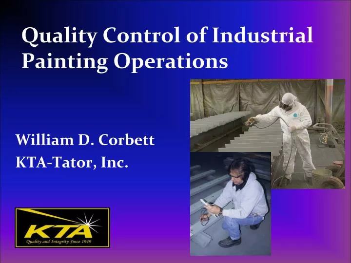
Quality Control of Industrial Painting Operations. William D. Corbett KTA-Tator, Inc. Webinar Content. Industry standards for coating application QC Developing a quality control plan for painting Navigating a Technical (Product) Data Sheet

E N D
Quality Control of Industrial Painting Operations William D. Corbett KTA-Tator, Inc.
Webinar Content • Industry standards for coating application QC • Developing a quality control plan for painting • Navigating a Technical (Product) Data Sheet • Measuring ambient conditions and surface temperature • Witnessing mixing, thinning and application procedures • Calculation and measurement of wet film thickness • Dry film thickness measurement • Post-application testing • Cure/hardness • Holiday/pinhole detection • Adhesion • Identifying application defects
Learning Objectives/Outcomes • Completion of this webinar will enable the participant to: • Describe the industry standards that pertain to coating application • Prepare a Quality Control Plan for painting • Describe the content of a Technical (Product) Data Sheet • Measure environmental conditions and surface temperature prior to coating mixing • Evaluate mixing, thinning and application procedures • Calculate and measure wet film thickness • Measure dry film thickness • Perform post-application testing
Industry Standards for Coating Application • SSPC-PA 1 Shop, Field and Maintenance Painting of Steel • SSPC-PA 2 (frequency and tolerance of coating thickness measurements on steel) • SSPC-PA 9 (frequency and tolerance of coating thickness measurements on concrete) • ASTM E337 (use of whirling/aspirating psychrometers) • ASTM D4414 (wet film thickness measurement) • ASTM D7091/D6132 (dry film thickness measurement) • ASTM D5402/D4752/D3363/D1640 (drying, curing, hardness) • ASTM D5162/D4787 (holiday/pinhole detection) • ASTM D3359/D6677/D4541/D7234 (adhesion)
SSPC Paint Application Specification No. 1 (PA 1) • Shop, Field and Maintenance Painting of Steel • Common specification reference • Contains 14 Sections: • Scope 8. Shop Coating • Description 9. Field Coating • Referenced Standards 10. Repair of Damaged Coatings • Definitions 11. Appl. Proc. For Coatings • Pre-application Procedures 12. Curing & Handling • Factors Affecting Application 13. Inspection • Application Methods 14. Safety & Environmental
Purpose of a Quality Control Plan • Provides QC Inspector with: • A systematic inspection and testing plan that covers all phases of work in sequence • A written document that lists what to inspect, how to inspect and the acceptance criteria • A tool to enable an inspector to navigate through and extract inspection check points from the specification • May be a required contract submittal
Benefits of a Quality Control Plan • Coating specifications can be complex documents • Specifications typically contain the quality requirements for a coatings project • Good inspection doesn’t happen by accident; it requires planning • QC plans make specification compliance more streamlined and complete • Provides a key communication tool between QA and QC inspection personnel
Product Data Sheets • Prepared by the coating manufacturer • An “instruction manual” for the coating • Technical & marketing information about the coating • ASTM F 718 provides a standard specification for marine paints
Product Data Sheets, con’t. • Typically contain: • Brand name of the product • Generic type of the coating • When/where the coating can be used • Compatible coatings • Product weight and volume solids content • Theoretical coverage rate
Product Data Sheets, con’t. • Often contain: • Recommended level(s) of surface preparation • Recommended dry film thickness • VOC content of the coating (as manufactured) • Adjusted VOC content dependant on amount and type of thinner • Performance data (adhesion, abrasion resistance, etc.) • Recommended methods of application • Mixing and thinning instructions • Pot life, induction time • Drying times (dry to handle, dry to recoat) • Cure times • Recoat times • Method to verify cure
Product Data Sheets Vs. Specification Requirements • Product data sheets contain recommendations • When the PDS and the project specification differ, the specification is the governing document (contract) • The specification may invoke the PDS • QC inspector should note discrepancies/vague information and advise the owner at the bidding stage and at the pre-job meeting
Environmental Conditions for Coating Application • Air Temperature (min. & max.) • Relative Humidity (min. or max) • Dew Point Temperature • Surface Temperature [min. 5°F (3°C)] above Dew Point Temperature • Wind Speed (max.)
Significance of Conditions • Air Temperature • Too cold or too hot can affect coating application & curing • Relative Humidity • Too damp or too dry can affect coating application & curing • Surface Temperature • Too cold or too hot can affect application & curing • Surface temperature at or below dew point temperature will result in condensation
Significance of Conditions, con’t. • Wind Speed • Too windy can affect application (dry spray) and cause overspray damage • Mixing/application of coatings under adverse weather conditions can void the manufacturer’s warranty and is considered a specification non-conformance
Ambient Conditions & Surface Temperature • Measuring Instruments • Sling Psychrometers* • Battery-powered Psychrometers* • Electronic Psychrometers • Analog, Thermocouple-type & Non-contact Surface Thermometers * Used in conjunction with psychrometric charts or calculators
Using Sling Psychrometers • ASTM E337 • Verify wick cleanliness • Saturate wick and/or fill reservoir with DI water • Whirl 20-30 second intervals until wet bulb stabilizes (2 readings within 0.5o) • Record wet & dry bulb temperatures
Using Psychrometric Charts • Locate Chart (relative humidity or dew point) • Verify Barometric Pressure (e.g., 30.0 in.) • Intersect air temperature with wet bulb depression (Ta-Tw) • Calculators (bottom image) can also be used
Electronic Psychrometers • Measure/Record: • Air Temperature • Surface Temperature (ST) • Relative Humidity • Dew Point Temperature (DP) • Spread between DP and ST • Features • Auto-logging allows for automatic data collection • Magnetic surface probe • Data graphing and Blue Tooth uploading • Audio/visual alarm
Measuring Surface Temperature • Dial-Type Thermometer • Position & stabilize for minimum of 2 minutes • Thermocouple-Type Thermometers • Stabilize quickly • Infrared (non-contact) thermometers • Watch distance
Assessing Wind Speed • Analog wind meters • Digital wind meters • Rotating Vane Anemometers • Air flow inside containment • Wind speed
Significance of 5°F (3°C) • Theoretically, a small (<1°F) increase (surface temperature over dew point) will preclude moisture formation • Minimum increase of 5°F (3°C) compensates for: • Instrument tolerances • Varying conditions • Changing conditions
Location and Frequency of Data Acquisition • Location • Dictated by where the work is being performed (e.g., inside vs. outside of a containment; balcony of elevated storage tank vs. ground level) • If interior, with ventilation in operation • Shops: Blast or Paint bay area • Frequency • Prior to mixing of coatings • Four-hour data collection intervals is common • More frequent measurement if conditions are changing
Inspecting Mixing Procedures • Verify components are within the manufacturer’s shelf life (and stored properly) • Check PDS for mixing instructions • Measure coating temperature after all components are thoroughly blended • Straining required? • Thinning required/allowed? • Induction time required? • Pot life monitoring
Inspecting Thinning Procedures • Verify: • Correct type of thinner is used • Calculation of thinner quantity is accurate • Graduated containers are used to measure thinner • Consider impact on local VOC regulations
Calculating the Target Wet Film Thickness • Sometimes the wet film thickness will be listed on the PDS (many times it is not) • Arriving at the target wet film thickness is necessary to arrive at the specified dry film thickness • Must be adjusted based on the amount of thinner added
Calculating a Target Wet Film Thickness • Calculating Target Wet Film Thickness WFT = Target DFT % solids by volume Example: 5 mils DFT 68% solids by volume (0.68) Target wet film thickness: 7-8 mils
Calculating a Target Wet Film Thickness • Effect of Thinner Addition on WFT Target • WFT = Target DFT % solids by volume 100% + % thinner
Calculating a Target Wet Film Thickness • Effect of Thinner Addition, continued • WFT = 5 mils DFT 0.68 100% + 20% thinner 5 mils DFT5 mils DFT 68 = 0.57 = 9 mils WFT 120
Measuring Wet Film Thickness • ASTM D 4414 – “Practice for Measurement of Wet Film Thickness by Notch Gages” • Place gage into wet coating immediately • Withdraw gage and read highest wetted step (e.g., 5 mils) • Immediately clean coating from gage
Measuring Dry Film Thickness • Three common standards that address the nondestructive measurement of coating thickness : • Ferrous and nonferrous metals: ASTM D 7091 • Steel only: SSPC-PA 2 (2004) • 2012 version will address ferrous and nonferrous metals • Non-metal surfaces • ASTM D 6132 • SSPC-PA 9
Measuring Dry Film Thickness • Standards provide procedures for: • Calibration (gage manufacturer/approved lab) • Frequency of verifying gage accuracy (user) • Frequency of measurements (number of measurements to obtain based on the size of the structure) • SSPC-PA 2 places limits on spot and area readings vs. specified thickness
Measuring Dry Film Thickness (SSPC-PA 2) • Requires calibration by manufacturer (typically annual) • Certificate of calibration traceable to a National Metrology Institute required • Verification of accuracy (by user) before and after each period of use • Two types of nondestructive coating thickness gages • Magnetic pull-off (Type 1) • Electronic (Type 2)
Verifying Type 1 Gage Accuracy • Use calibration blocks • NIST Traceable • Proprietary from gage manufacturers • Verify accuracy: • In range of use • Before and after each period of use • Must correct for surface roughness (BMR)
Verifying Type 2 Gage Accuracy • Use calibration blocks or shims • Verify accuracy in range of use • Most can be adjusted • Follow gage manufacturer’s instructions (vary)
Verification of Type 2 Gage Accuracy • If smooth reference standards are used (A), user must correct* for surface roughness • If shims (foils) are used (over the prepared steel; B), no correction is needed *Via Base Metal Reading (BMR) A B
Measurement Frequency • Terminology: • Gage Reading: A single reading at one location • Spot Measurement: The average of at least 3 gage readings made within a 1.5” diameter circle • Area Measurement: The average of 5 spot measurements made within a 100 square foot area
Dividing Structures into Test Areas • If the structure is less than 300 square feet, each 100 square feet is measured • If the structure is between 300 and 1000 square feet, select 3 random 100 square foot test areas and measure • For structures exceeding 1000 square feet, select 3 random 100 square feet testing areas for the first 1000 square feet, and select 1 random 100 square foot testing area for each additional 1000 square feet
Example: Structure Size: 55,000 square feet No. of Areas: 3 + 54 = 57 areas No. of Spots: 57 Areas x 5 Spots/Area = 285 Spots No. of Gage Readings: 285 Spots x 3 Readings/Spot = 855 Gage Readings
Coating Thickness Tolerance (SSPC-PA 2) • Individual readings (averaged to create a spot measurement) are unrestricted • Non-repeating low or high readings can be discarded • The spot measurement (the average of 3) must be within 80% of the minimum thickness and 120% of the maximum • Area measurement must be within specified range
Assessing Intercoat Cleanliness • Airborne dust and/or abrasive may be deposited on coated surfaces • Problematic if surface is to be recoated • Requires visual or tactical (touch) examination of the surface
Verifying Recoat Times and Temperatures • Coating materials may have a minimum and/or a maximum recoat time • Verify: • Coating has been allowed to dry or cure the minimum amount of time • The next coat is applied before the maximum recoat time has been exceeded
Detecting Pinholes and Holidays • Definitions: • Holidays – skips or misses in the coating/lining system • Pinholes – tiny voids in the coating or lining • Standards: • ASTM D5162 and D4787; NACE RP01-88 • Conducted: • After final coat has been applied, but before it has achieved complete cure (touch-up) • Specifications may require holiday testing after the application of each coat • May cause intercoat contamination
Rules for Holiday Detection • Coating must be nonconductive • Substrate must be conductive • High voltage (spark) testing requires voltage setting • 100 to 125 volts/mil of coating • Obtain recommended test voltage from coating manufacturer • Excessive voltage can damage coating film
Holiday Detectors • Low voltage (wetted sponge) – coatings that are less than 20 mils thick • High voltage (spark tester) – coatings that are greater than 20 mils thick • Move wand/electrode maximum of one foot/second
Inspecting OAP Coating Systems • “Visual” pinhole/holiday detection • Optically Active Pigments (OAP) added to coatings during formulation • Inspection performed using UVA-340 light • Process described in SSPC TU 11 • Inspector training recommended if inspections not previously performed
Assessing Coating Drying/Cure • Pencil Hardness (ASTM D3363) • Solvent Resistance (Solvent Rubs; ASTM D5402) for convertible coatings • Solvent Resistance (Solvent Rubs; ASTM D4752) for ethyl silicate inorganic zinc primers • Impressor Hardness • Barcol Hardness (ASTM D2583) • Durometer Hardness (ASTM D2240) • Dry Time Testing (ASTM D1640)