Download
1 / 36
390 likes | 791 Views
Line Coding, Modem, RS232 interfacing sequences. Line Coding. Process of converting binary data to a digital signal. DC Components. Residual direct-current (dc) components or zero frequencies are undesirable

E N D
Line Coding • Process of converting binary data to a digital signal
DC Components • Residual direct-current (dc) components or zero frequencies are undesirable • Some systems do not allow passage of a dc component; may distort the signal and create output errors • DC component is extra energy and is useless
Self-Synchronization • Includes timing information in the data being transmitted to prevent misinterpretation Lack of synchronization
Line Coding • Unipolar • Polar • Bipolar
Unipolar • Simplest method; inexpensive • Uses only one voltage level • Polarity is usually assigned to binary 1; a 0 is represented by zero voltage
Unipolar • Potential problems: • DC component • Lack of synchronization
Polar • Uses two voltage levels, one positive and one negative • Alleviates DC component • Variations • Nonreturn to zero (NRZ) • Return to zero (RZ) • Manchester • Differential Manchester
Nonreturn to Zero (NRZ) • Value of signal is always positive or negative • NRZ-L • Signal level depends on bit represented; positive usually means 0, negative usually means 1 • Problem: synchronization of long streams of 0s or 1s • NRZ-I (NRZ-Invert) • Inversion of voltage represents a 1 bit • 0 bit represented by no change • Allows for synchronization
Return to Zero (RZ) • In NRZ-I, long strings of 0s may still be a problem • May include synchronization as part of the signal for both 1s and 0s • How? • Must include a signal change during each bit • Uses three values: positive, negative, and zero • 1 bit represented by positive-to-zero • 0 bit represented by negative-to-zero
RZ Encoding • Disadvantage • Requires two signal changes to encode each bit; more bandwidth necessary
Manchester • Uses an inversion at the middle of each bit interval for both synchronization and bit representation • Negative-to-positive represents binary 1 • Positive-to-negative represents binary 0 • Achieves same level of synchronization with only 2 levels of amplitude
Differential Manchester • Inversion at middle of bit interval is used for synchronization • Presence or absence of additional transition at beginning of interval identifies the bit • Transition means binary 0; no transition means 1 • Requires two signal changes to represent binary 0; only one to represent 1
Bipolar Encoding • Uses three voltage levels: positive, negative, and zero • Zero level represents binary 0; 1s are represented with alternating positive and negative voltages, even when not consecutive • Alternate mark inversion (AMI)
Bipolar AMI • Neutral, zero voltage represents binary 0 • Binary 1s represented by alternating positive and negative voltages
Telephone Modems • A telephone line has a bandwidth of almost 2400 Hz for data transmission
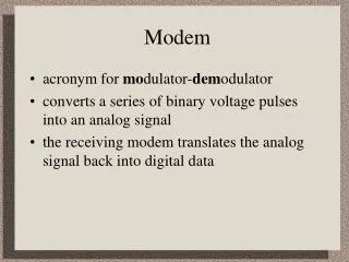
Modem stands for modulator/demodulator. • Modulator : creates a analog signal from binary data • Demodulator : recovers the binary data from the modulated signal
V.32 • ITU-T's V.32 standard was issued in 1989 for asynchronous, full-duplex operation at 9600 bps. • Although designed for asynchronous DTEs, two V.32 modems actually communicate synchronously. • A circuit converts the asynchronous data stream into synchronous blocks, invisible to the application. • V.32 supports modulation rates of 2400, 4800, and 9600 bps.
V.32bis • ITU-T's V.32 standard was issued in 1991 for asynchronous, full-duplex operation at 14.4 Kbps. • V.32bis is an extension of the V.32 technology. V.32bis supports modulation rates of 2400, 4800, 9600 bps and 14.4 Kbps. • Data compression and error correction can increase the throughput rates.
Traditional Modems • After modulation by the modem, an analog signal reaches the telephone company switching station where it sampled and digitized to be passed through the digital network. • Bit rate is 56,000bps. • Uploading :33.6kbps. • Downloading 56kbps.
Introduction • Specifies the interface between DTE and DCE: • V.28 : mechanical and electrical characteristics • V.24 : functional and procedural characteristics • Even used in applications where there is no DCE • e.g. connecting computer to printer, magnetic card reader, robot, … etc. • Introduced in 1962 but is still widely used
Vocabulary • DTE • data terminal equipment • e.g. computer, terminal • DCE • data communication equipment • connects DTE to communication lines • e.g. modem
Mechanical Characteristics • 9-pin connector • 9-pin connector is more commonly found in IBM-PC but it covers signals for asynchronous serial communication only • Use male connector on DTE and female connector on DCE • N.B.: all signal names are viewed from DTE
Electrical Characteristics • Single-ended • one wire per signal, voltage levels are with respect to system common (i.e. signal ground) • Mark: –3V to –15V • represent Logic 1, Idle State (OFF) • Space: +3 to +15V • represent Logic 0, Active State (ON) • Usually swing between –12V to +12V • Recommended maximum cable length is 15m, at 20kbps
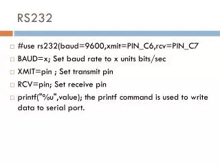
RS-232 Interface RS-232 is the Serial interface on the PC • Three major wires for the Serial interface: • Transmit - Pin 2 • Receive - Pin 3 • Ground - Pin 7 (25 pin connector) - Pin 5 (9 pin connector) Tx Tx Computer Device Rx Rx Gnd Gnd Transmit connects to Receive
Function of Signals • TD: transmitted data • RD: received data • DSR: data set ready • indicate whether DCE is powered on • DTR: data terminal ready • indicate whether DTR is powered on • turning off DTR causes modem to hang up the line • RI: ring indicator • ON when modem detects phone call
Function of Signals • DCD: data carrier detect • ON when two modems have negotiated successfully and the carrier signal is established on the phone line • RTS: request to send • ON when DTE wants to send data • Used to turn on and off modem’s carrier signal in multi-point (i.e. multi-drop) lines • Normally constantly ON in point-to-point lines • CTS: clear to send • ON when DCE is ready to receive data • SG: signal ground
Flow Control • Means to ask the transmitter to stop/resume sending in data • Required when: • DTE to DCE speed > DCE to DCE speed (e.g. terminal speed = 115.2kbps and line speed = 33.6kbps, in order to benefit from modem’s data compression protocol) • without flow control, the buffer within modem will overflow – sooner or later • the receiving end takes time to process the data and thus cannot be always ready to receive