Download
1 / 46
560 likes | 812 Views
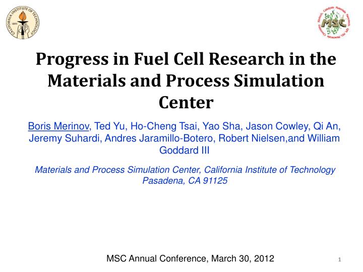
Progress in Fuel Cell Research in the Materials and Process Simulation Center. Boris Merinov , Ted Yu, Ho-Cheng Tsai, Yao Sha, Jason Cowley, Qi An, Jeremy Suhardi, Andres Jaramillo-Botero, Robert Nielsen,and William Goddard III

E N D
Progress in Fuel Cell Research in the Materials and Process Simulation Center Boris Merinov, Ted Yu, Ho-Cheng Tsai, Yao Sha, Jason Cowley, Qi An, Jeremy Suhardi, Andres Jaramillo-Botero, Robert Nielsen,and William Goddard III Materials and Process Simulation Center, California Institute of Technology Pasadena, CA 91125 MSC Annual Conference, March 30, 2012 1
Computational Methods • - Bridging the Gap between QM and Large-Scale MD • Simulate bond break and formation in large system Atoms Molecular conformations years ReaxFF Design Electrons Bond formation FEA Time MESO Grids MD Grains QC Force Field MD 10-15 ab initio, DFT,HF Ångstrom Meters Distance • - QM Calculations – DFT(PBE) with • SeqQuest • Allows calculations on small systems • with ~100 atoms • ReaxFF Calculations – Molecular • Dynamics Simulations • Allows larger systems up to ~4000 • atoms. • A parallel version of ReaxFF allows • multimillion atom MD simulations The goal of our computational work is to develop atomistic models for fuel cell systems based on the application of first-principles theory and useful for prototyping new systems computationally prior to experiment. Our strategy for achieving these goals is to develop overlapping simulation methodologies, which are based on first principles and use a sequence of overlapping paradigms each built on the more fundamental level that ultimately can accurately predict phenomena at the appropriate scales.
Atomistic Modeling in Fuel Cell Development First-Principles based predictions of: • Atomistic details of structures of electrolyte, electrodes, and their interfaces • Mechanisms of chemical and electrode processes • Pathways, energetics, and rates • How electrical and ionic conductivities depend on materials • Pathways, energetics and rates Fuel cell research in the MSC focuses on computational modeling of 1) Pt-based and non-Pt catalysts, such as Pd- and Ni-based catalysts, for applications in low-, medium- and high-temperature fuel cell systems, 2) solid electrolytes, such as Nafion, oxide-ion-conducting yttria-stabilized zirconia, proton-conducting Y-doped barium zirconate, and hydroxide-ion conducting polymer membranes for alkaline fuel cells, 3) chemical processes related to membrane degradation, and electrode/electrolyte interfaces.
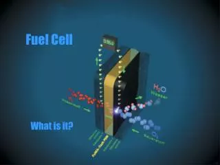
Modeling Paradigm for Optimization of Fuel Cell Systems Atomistic view of a polymer electrolyte membrane fuel cell (PEMFC)
Low-temperature Polymer Electrolyte Membrane Fuel Cell (PEMFC): Nafion Membrane Degradation (Funded By Ford)
Nafion Degradation Physical Degradation Chemical Degradation Unclear of Mechanism? OH and OOH radical formation? Site of chemical degradation unclear • Membrane Creep • Microcrack Fracture • Pin Hole Formation at high T • Morphological Changes Anode Cathode Damage at Interface Nafion After Before
Nafion Chemical Degradation Backbone The backbone of Nafion is a Teflon chain that consists of (CF2)n. This backbone is very durable chemically. However, Fenton tests suggest that degradation is greater at the backbone because of end groups of -CF=CF2, CF2-CF3H, and COOH that occur as a result of the manufacturing process. [Curtin et al. J. Power Sources 131 (2004) 41–48] Sidechain • Nafion degradation work conducted to simulate an actual fuel cell environment observed significant products of the sidechain: • Reduction of –OCF2 and -SCF2 groups by FNMR and –O-CF and -S-CF2 groups in the outlet water • [Ghassemzadeh et al. J. Phys. Chem. C, 114 (2010) 14635–14645] • Observation of SO2 and H2SO3 in the outlet water by mass spectroscopy • [Teranishi et al. Electrochem. & Solid State Lett, 9 (2006) A475-A477].
Difference between Fenton Test and Degradation from Fuel Cell Operation • Degradation experiments performed by DuPont applied Fenton tests, where the concentration of OH radical is very high. • We must differentiate between environments of: • Fenton test: where concentration of OH radical is high. There is no H2 or O2, which means there is likely no H radicals. • Fuel Cell Condition: where there is trace OH radical but enough O2 and H2. We limit these mechanisms to have only one OH radical as a reactant. H radical can be formed by OH + H2 => H2O + H • As we hypothesized in our paper,* trace OH radicals come from the Pt catalyst surface and not from Fenton reagents that are created in the Nafion membrane. *Yu, Sha, Liu, Shrivanian, Merinov, Goddard. JACS, 2011
Summary of Barriers and Conclusions • Mainchain degradation is much easier than sidechain degradation in Fenton environment • Mainchaindegradation is easier in Fenton environment than in FC environment • Sidechain degradation is easier in FC environment than in Fenton environment • Replacement of vulnerable F on Tertiary Carbon with CH3 group may help to improve chemical stability of Nafion
Alkaline Fuel Cell: Low-temperature Hydroxide Exchange Membranes (Funded by Samsung) 10
Hydroxide-ion Conducting Alkaline Fuel Cells Schematic depiction of AFC Advantages of polymer AFCs over PEMFCs enable application of non-precious metal catalysts for electrodes. During last 2-3 years high-performance alkaline polymers, quaternary ammonium polysulphone (QAPS-OH) and tris(2,4,6-trimethoxyphenyl)polysulfone-methylene quaternary phosphonium hydroxides (TPQPOH), have successfully been synthesized and applied for polymer Alkaline Fuel Cells (AFCs)
Microstructure of QAPS-OH Alkaline Polymer Electrolyte The QAPS-OH structure from the MD simulations (Dreiding FF, 3456 atoms, 48 OH, d=0.85 g/cm3 annealing from 300 to 600K, using the procedure similar to that describe in S.S. Jang et al. J. Phys. Chem. B 108, 3149 (2004)
OH-diffusion in QAPS-OH Alkaline Polymer Electrolyte Diffusion coefficients (cm2/sec) for dry and hydrated (15%wt water uptake) QAPS-OH membranes at different temperatures and corresponding activation energy (eV). Diffusion coefficients (theory) Conductivity(experiment) 5·10-2 S/cm 15wt% H2O QAPS-OH with 15%wt H2O, T=300K, exp.: σ 1.2 ·10-2 S/cm, Ea = 0.14 eV [J. Pan et al. Adv. Funct. Mater. 20, 312 (2010)] Our computational results are in good agreement with experiment. For example, the calculated conductivity that corresponds to the diffusion coefficient in hydrated (15%wt water uptake) membrane at T=300K is 5 · 10-2 S/cm and activation energy Ea = 0.11 eV.
Ongoing Calculations • Build dry and solvated microstructures (0-40% in 5% increments) with methylimidazolium, ethylimidazoilum benzylimidazolium, and butylimidazolium side chains at different temperatures • Calculate diffusion coefficients for water, hydroxide-ion and hydrogen • Introduction of effective polymer cross-linkers [e.g., tetramethylethylenediamine (TMEDA)]
Intermediate-temperature Proton Ceramic Fuel Cell (PCFC): Y-doped BaZrO3
Proton Conductivity of Doped BaZrO3 (BYZ) K.-D. Kreuer, Annu. Rev. Mater. Res. 33, 333 (2003) At present, only electrolytes based on Y-doped BaZrO3 (BYZ) combine high bulk proton conductivity with excellent chemical stability. The reason why the high proton conductivity of the Y-doped BaZrO3 electrolyte has been revealed relatively recently is because conductivity measurements for this class materials are usually performed on ceramic specimens at high temperatures where only total resistivities are accessible. But this electrolyte has a large amount of grain boundaries that have much lower conductivity.
Effect of Grain Boundaries on Proton Diffusion in BYZ HRTEM of BaZr0.85Y0.15O2.925 with (111) and (110) lattice planes (Groβ et al., Solid State Ionics v.145, pp.325, 2001) Hydrogen diffusion coefficients MD conditions • Using ReaxFF • NVT ensemble (T=1000, 1250, 1500, 1750 and 2000K) • Time step=0.25 fs, final=200 ps • Total numbers of atoms=872 (H: 16) Ea=0.66 eV Ea=1.12 eV
Grain Boundary Structural Characteristics After quenching from 1000 K The cation-oxygen distances in grain boundary cores are almost identical to those of the grain interior Grain Grain boundary Grain Grain boundary • - O atoms are deficient in the grain boundaries relative to grain interiors • The oxygen-oxygen distances in the grain boundary are longer than in the grain • Longer oxygen-oxygen distances increase barriers for the proton transfer Zr-O distance and coordination (a) inside grains (b) in grain boundary core. Strategy for improving the diffusion performance of multigranular BYZ: find additives that would tend to precipitate to the grain boundary while pulling oxygen atoms closer.
High-temperature Solid Oxide Fuel Cell (SOFC): Fuel/Electrode/Electrolyte Interface
Modeling of Oxide-ion Diffusion in YSZ EXPERIMENT: YSZ-10: Ea = 0.99 eV Do = 3.4 ·10-3cm-2s-1 [M. Kilo et al. Phys. Chem. Chem. Phys. 5, 2219 (2003)] THEORY: YSZ-14: Ea = 0.90 eV Do = 2.4 ·10-3cm-2s-1 ReaxFF Development Ni-H and Ni-O interactions for Ni(111) surface QM and ReaxFF Energies for Various YSZ Configurations • QM data shows that Pt prefers H-top, while Ni prefers H-fcc • ReaxFF can reproduce the QM-data for both Pt and Ni Calculated and Experimental Oxide-ion Diffusion Coefficients in YSZ Trajectory of one oxygen atom in YSZ. ReaxFF MD simulation, T=2000 K, ~400 ps. Oxygen diffusion coefficients Excellent agreement between experiment and theory
YSZ/Ni/H2 Triple Phase Boundary: ReaxFF MD Simulation, 1250 K, 150 ps Ending point: YSZ and YSZ/Ni: 87xH2, 5xH2O, 11xOH on YSZ, 3xOH on YSZ/Ni interface Ni-anode: 240xNi, 22xO on Ni, 51xH on Ni, 1xOH on Ni Starting point: 20xC4H10 1xNi240+Y16Zr48O148 H2 gas H2O H2O H2O YSZ Ni-anode H2O • 5 H2O, 51 H atoms on the Ni-surface, 22 Ni-O bonds (Ni-oxidation), and only 1 Ni-OH group, while substantial reduction of the YSZ electrolyte, resulting in formation of 11 hydroxyl groups on the YSZ surface and 3 at the Ni/YSZ interface, was observed. • ReaxFF RD simulation also indicates amorphization of the Ni, at least its surface, and partial decohesion (delamination) at the interface observed in experiment. 21
YSZ/Ni/H2 Triple Phase Boundary: ReaxFF MD Simulation, 1250 K, 150 ps H2O Formation on YSZ/Ni interface Water formation at the interface, and H2 going to Ni-H
YSZ/Ni/H2 Triple Phase Boundary: ReaxFF MD Simulation, 1250 K, 150 ps H2O Formation on Ni-surface Delamination Delamination and water flow away from Ni (experimentally validated)
YSZ/Ni/Butane Triple Phase Boundary: ReaxFF MD Simulation, 2000 K Butane YSZ Ni Starting point: 20 x C4H10 1 x Ni240 + Y16Zr48O148 Butane Conversion: Products found are in very good agreement with experimentally observed products of the n-butane pyrolysis: ReaxFF properly describes the water formation reaction and allows first-principles predictions of the chemical processes at the YSZ/Ni/fueltriple phase boundary
Fuel Cell Catalysts: Pt-based and non-Pt (Funded by Ford, NSF and DOE) 25
Two Mechanisms for ORR on Pt (111) Surface O2-dissociation mechanism: OOH-association mechanism: Gas Phase: ORR on the Pt(111) has a total energy barrier of 0.74 eVwith the OH formation as the RDS for both the O2-dissociation and OOH association mechanisms. Solvent effect significantly modifies the reaction energies and ORR barriers for both mechanisms. RDS for both mechanisms is the OH formation step with a barrier of 0.97 eV in water solvent. O2 –dissociation mechanism: O2g O2ad (no barrier) O2ad2Oad [Eact = 0.00 eV (Pt), 0.27 (Pd)] Oad + HadOHad[Eact = 0.97 eV (Pt), 0.47 (Pd)] OHad + Had H2Oad[Eact = 0.24 eV (Pt), 0.78 (Pd)] OOH-association mechanism: Had + O2ad HOOad [Eact = 0.22 eV (Pt), 0.74 (Pd)] HOOad HOad + Oad[Eact = 0.00 eV (Pt), 0.10 (Pd)] Oad + HadOHad[Eact = 0.97 eV (Pt), 0.47 (Pd)] OHad + Had H2Oad[Eact = 0.24 eV (Pt), 0.78 (Pd)] T. Jacob, W.A. Goddard, ChemPhysChem 2006, 7, 992–1005.
ORR Pathways on Pt (111) Surface Direct O2 dissociation: (I) OOH association: (II) New mechanisms: Avoid OH formation! H-associated OOH dissociation: (III) Avoid OH formation! O hydration: (IV) (V) 0.00 0.57 Regular: barriers in gas phase Italic: barriers in solution O-hydration-solv mechanism: O2g O2ad (no barrier) O2ad 2Oad [Eact = 0.00 eV (Pt), 0.27 (Pd)] Oad+H2Oad2OHad [Eact= 0.50 eV (Pt), 0.49 (Pd)] OHad + Had H2Oad [Eact=0.24 eV (Pt), 0.78 (Pd)] O hydration is the RDS with a barrier of 0.50 eV for Pt. For Pd the RDS is H2O formation with a barrier of 0.78 eV, consistent with the decreased performance of Pd. This new mechanism suggests that a strategy for improving efficiency of ORR catalysts is to focus on decreasing Eact for the Oad hydration step.
Modeling ORR under Potential E = Egas(+q) + Esolv + EF(NHE) + qU • Since partial charge is possible in DFT, scan the PES for system with charge 0, +0.1, …, +1.0 • Assuming that the electron taken out is put back into Fermi level to put all the PES into the same scale. • Pick the optimal charge for each image in NEB to find out when electron transfer happens. • Allow Had and H+ to compete. The energy surface for the reaction Oad + H++ e− → OHad in which charge and OH formation are considered as two independent coordinates. The green curve gives an optimal reaction path at U = 1.0 V. Predicted power output as a function of electrode potential. Barriers for the 4 steps of the ORR. All barriers become higher as electrode potential increases. Here OH formation is the RDS for ORR. Y. Sha, T. Yu, B.V. Merinov, W.A. Goddard, J.Phys.Chem. C. 2012, 115, 6166-6173
Improved Oxygen Reduction Reaction (ORR) on Pt3Ni(111) Surface characterization of a Pt3Ni single crystal in UHV and electrochemical environments The Pt3Ni(111) skin surface exhibits the highest catalytic activity that has ever been detected. The challenge is to create a stable nanocatalyst with electronic and morphological properties that mimic the Pt3Ni(111) surface. Stamenkovic et al. , Science 315, 493 (2007)
Pt Alloys: Segregated vs. Uniform Alloying Pt with these metals provides good surface segregation and formation of Pt-skin
Oxidation of Pt3Co Alloys • The subsurface Co in Pt3Co catalysts leach onto the surface and into the solution during extended fuel cell operations. • Over time, the subsurface layers become Co free, and this renders these layers to contain only Pt. Dubau, L.; Maillard, F.; Chatenet, M.; Guetaz, L.; Andre, J.; Rossinot, E. J Electrochem Soc2010, 157, B1887.
Pt Segregation with O on Surface Our study shows that Pt3Ir and Pt3Os can remain segregated in the presence of O on the surface Pt3Co and Pt3Ni is vulnerable to oxidation with O on surface
Pt Segregation with OH on Surface These Pt alloys can remain segregated in the presence of OH on the surface Pt3Co and Pt3Ni is vulnerable to oxidation with OH on surface
Strategy for Development of New Efficient Catalysts Balance the barrier for O2 dissociation, OH formation (O hydration) and H2O formation Binding energy of O and OH Low barrier for RDS Catalyst needs to be stable under the operating condition: Nobel metal needs to be on top to form skin Large surface segregation Ternary alloys with a third metal that stabilize bulk and surface structures of efficient binary alloys Develop new thin film core-shell catalysts
W(110) Surface and Binding Sites on Pt/W(110) Pt bond-length = 2.81 Å Lattice misfit for shorter bonds = -1.42% Lattice misfit for the longer bond =13.88% Surface misfit = 5.85% 2.77Å μ3c μ2-L 2.77Å • Why we use W(110) as substrate: • Surface energy: W has a high surface energy (3300 erg/cm2K) compared to Pt (2550 erg/cm2K). • Lattice mismatch: Pt deposited on W is going to experience compression by 1.42% due to lattice mismatch. It may change binding energy of intermediates on Pt. • Lower binding energy: Binding energies decrease under compression and increase under extension of Pt. The lattice misfit between Pt(111) and W(110) may induce surface Pt compression which may result in lower binding energies. 3.20Å μ3h 70.53O μ1 μ2-S
1 to 5 Layer Pt/W(110) Surface 1 2 3 3.17 5 2.77 3.21 2.77 2.77 2.77 2.77 3.28 4 2.77 3.13 3 ABAB stacking series up to 4 Pt layers and ABC stacking series similar to Pt(111) after 5 layer Pt deposition 2.77 3.21 2.78 2.77 2.77 2.99 3.42 2.77 2.78
Binding Energies of Intermediates for Different Numbers of Pt Layers on W(110) Binding energy for H, O and HOH becomes stable when the number of Pt layers ≥ 3. However, its values are higher than those for Pt(111). Binding energy for OH and OO becomes stable when the number of Pt layers ≥ 4. It is unstable for OOH, maybe due to the surface geometry change resulting from the interaction between surface Pt and OOH. All values are higher than for Pt(111).
Efficiency Prediction for Different Mechanisms in Gas Phase O2-diss-gas mechanism: • O2g ---> O2ad no barrier • O2ad --->2Oad Ea, Pt = 0.58 eV, Ea, Pt-W = 0.24 eV • Oad + Had ---> OHad Ea, Pt = 0.72eV, Ea, Pt-W = 0.75 eV • OHad + Had ---> H2Oad Ea, Pt = 0.11 eV,Ea, Pt-W = 0.07 eV HOO-form-gas mechanism: • O2g ---> O2ad no barrier • Had + O2ad --->HOOad Ea = 0.28 eV,Ea, Pt-W = 0.30 eV • HOOad ---> HOad + Oad Ea = 0.14 eV,Ea, Pt-W = 0.03 eV • Oad + Had ---> HOad Ea = 0.72 eV,Ea, Pt-W = 0.75 eV • OHad + Had ---> H2Oad Ea = 0.11 eV,Ea, Pt-W = 0.07 eV HOO-form-hydr-gas mechanism: • O2g ---> O2ad no barrier • Had + O2ad --->HOOad Ea = 0.28 eV, Ea, Pt-W = 0.30eV • HOOad ---> HOad + Oad Ea = 0.14 eV, Ea, Pt-W = 0.03 eV • Oad + H2Oad ---> 2OHadEa = 0.29 eV, Ea, Pt-W = 0.26 eV • OHad + Had ---> H2Oad Ea = 0.11 eV, Ea, Pt-W = 0.07 eV Pt/W(110) is slightly worse than Pt(111)
Efficiency Prediction for Different Mechanisms in Solution O2-diss-solv mechanism: • O2g ---> O2ad no barrier • O2ad --->2Oad Ea, Pt = 0.00 eV,Ea, Pt-W = 0.22 eV • Oad + Had ---> OHad Ea, Pt = 1.09 eV,Ea, Pt-W = 1.40eV • OHad + Had ---> H2Oad Ea, Pt = 0.17eV,Ea, Pt-W = 0.22 eV HOO-form-solv mechanism: • O2g ---> O2ad no barrier • Had + O2ad --->HOOadEa = 0.19 eV,Ea, Pt-W = 0.30 eV • HOOad ---> HOad+ Oad Ea = 0.00eV,Ea, Pt-W = 0.00 eV • Oad + Had ---> HOadEa = 1.09eV,Ea, Pt-W = 1.40eV • OHad + Had ---> H2Oad Ea = 0.17 eV,Ea, Pt-W = 0.22 eV HOO-form-hydr-solv mechanism: • O2g---> O2ad no barrier • Had + O2ad --->HOOadEa = 0.19eV,Ea, Pt-W = 0.30eV • HOOad ---> HOad+ OadEa = 0.00 eV,Ea, Pt-W = 0.00 eV • Oad + H2Oad ---> 2OHad Ea = 0.50eV,Ea, Pt-W = 0.68 eV • OHad + Had ---> H2Oad Ea = 0.11 eV,Ea, Pt-W = 0.07 eV Pt/W(110) is worse than Pt(111)
Conclusions • Our calculation results are in agreement with literature data which claim that influence of the ligand effect on the binding energy is negligible for 4 or more layers of Pt on substrate • Strong binding energy calculated for some intermediates and high barriers, in particular in solution, makes Pt/W(110) a worse catalyst than Pt • Other substrates with high surface energy and a smaller lattice constant should be tested. Perhaps, Mn and Mn-alloys, such as Mn3Ir which has the Cu3Au structure and a lattice constant of 3.79 Å might be considered as possible candidates for substrate. Further calculations are needed to test these and other possible materials.
Advanced Carbon Direct Conversion (ACDC) (Funded by DARPA)
Advanced Carbon Direct Conversion (ACDC) • ENVISIONED DEMONSTRATION: Computationally identify non-noble metal based nanostructures that will efficiently cleave C-C bonds of alkanes. • APPROACH: • Create database of parameters and possible materials critical for catalytic oxidation of alkanes. • Develop ReaxFF model suitable for oxidation of alkanes. • Optimize catalyst/electrolyte and nanoparticle structures. • Top-down approach: use generic force field parameters to determine best combination of metal-carbon, metal-hydrogen, metal-oxygen parameters lead to the lowest energy barriers, then focus on the metals closest to having these parameters to find best combination. Seedling efforts will demonstrated feasibility of these approaches or clarify what challenges remain – significantly reducing risk of a full program.
Butane C-C bond Breaking on Ni(111) surface Initial work has focused on understanding the C-C bond breaking mechanism on the Ni(111) surface at different temperatures to start optimization process. Continuous heating of the system linearly from 1250 K to 1500 K within 100 ps 1250 K 1500 K C-C bond breaking mechanism: First C-H bond break: E1 = E(surf) – E(separate) = E(Ni-C) + E(Ni-H) – E(C-H) = 8 kcal/mol Second C-H bond break: E2 = E(surf2) – E(separate) = 2[E(Ni-C) + E(Ni-H) – E(C-H) + E(strain) = 27 kcal/mol C-C bond break: E3 = E(surf3) – E(separate) = 41 kcal/mol. MD minimization using modified ReaFF(60% increased Ni-C sigma bond energy) Increased Ni-C bond strength leads to C-C bond breaking If we could find a metal, metal alloy or metal complex which binds to C atom by 42 kcal/mol more than Ni, it would break the C-C bond at room temperature.
Acknowledgement $$$ • NSF • DOE • Ford • Dr. Pezhman Shirvanian • Samsung • DARPA • Caltech-NCTU (Taiwan) Program