Download
1 / 21
210 likes | 368 Views
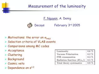
Measurement of CMS Luminosity. N. Adam, R. Hall-Wilton, V. Halyo, A. Heister, J. Hollar, A. Hunt, D. Marlow, A. Pozdynyakov, M. Schmitt, D. Stickland, M. Valesco, J. Werner, & Z. Xie , M. Zanetti. Overview. Methods for luminosity measurement at CMS: Online - HF Offline - HF & Vertex

E N D
Measurement of CMS Luminosity N. Adam, R. Hall-Wilton, V. Halyo, A. Heister, J. Hollar, A. Hunt, D. Marlow, A. Pozdynyakov, M. Schmitt, D. Stickland, M. Valesco, J. Werner, & Z. Xie, M. Zanetti
Overview • Methods for luminosity measurement at CMS: • Online - HF • Offline - HF & Vertex • Performance and comparison of methods • Absolute calibration using Van Der Meer Scans: • Introduction to the method • Scans & Results at CMS • Systematic Uncertainties • Results & Conclusion
Luminosity Measurement:Online - HF • CMS Luminosity is continuously measured (“KEEP_ALIVE”) using the forward hadronic calorimeters (HF) in two ways: • Tower occupancy measurement (2 × 2 h rings: 33-34L, 35-36L) • Total ET measurement (4 h rings: 33-34L + 35-36L) Single HF Tower (13) with alternating long (L) and short (S) fibers.
Luminosity Measurement:Online – Tower Occupancy • Start from formula relating luminosity to number of interactions, whereμ= mean number of interactions per BX,σ= pp cross-section, L = instantaneous luminosity and f = BX frequency. • For a noiseless calorimeter system, with p being the probability that a tower is not hit in a single interaction, it is easy to show that the average fraction of empty towers f0 goes as: • Accounting for noise is a non-trivial exercise that adds non-linear corrections. These are small (ε<<1) under certain conditions that our system meets. The final expression for the log of the empty tower fraction is linear with m. No. of interactions is Poisson with mean m Slope correction Non-linear, but small Noise offset For more details see: CMS IN-2007/030
Luminosity Measurement:Online – ET Sum • It is similarly possible to show that the average transverse energy sum per BX will also be linear with the number of interactions: • In this case there is no inherent non-linearity in the method. However, if truncation is used (as occurs in the Look-up Table (LUT)), extra non-linear terms are introduced. • The effect of this truncation is small (<2%) even over a very large range of luminosities, 1028 – 1034 cm-2s-1. Noise offset. ns gives the average energy of a single interaction bunch crossing. For more details see: CMS IN-2007/030
Luminosity Measurement:Offline – HF & Vertex • HF Offline (Zero Counting Method) • Require SET > 1GeV in both HF+ and HF- • Require |t| < 8ns in both HF+ and HF- • Vertex Counting Offline • Require ≥ 1 vertex with |z| < 15cm • Monte Carlo Efficiency Estimate
Absolute Calibration Method Luminosity can be accurately measured by scanning the beams across each other (separation scan method) and measuring the size and shape of the interaction region. [Method pioneered by S. Van Der Meer at ISR.] Note: method is in principal independent of the beam profile shape.
Absolute Calibration at CMS • The separation scan method is used for absolute calibration at CMS. Have 25 points per scan, out to ~4.5σ. • A double-Gaussian beam profile is needed to fit the beams observed in CMS. Significant luminosity in the tails of the distribution. • Luminosity at beam separation d is given by
Scans at CMS • Calibration scans were performed at CMS in fills 1386 and 1422. Preferred VdM scan with 4.5σ tails in fill 1386 only. • Fill 1386: 6 colliding bunches. • Single scan in each plane (X & Y). • Fill 1422: 3 colliding bunches. • Two scans in each plane XX then YY. • Scan optimized for alternate calibration method.
Online Scan Results: Fill 1386 All colliding bunches combined.
Online Scan Results: Fill 1386 All colliding bunches combined.
Online Scan Results: Fill 1386 Example individual BX = 1451
Online Scan Results: Fill 1422 All colliding bunches combined.
Online Scan Results: Fill 1422 All colliding bunches combined: X scans.
Online Scan Results: Fill 1422 All colliding bunches combined: Y scans.
Calibration & Absolute Luminosity Results To calibrate we use the central peak luminosity or “zero” points with all combination of measured beam widths. The measured beam widths are corrected for emittance blow-up. Final points on each plots are the average normalization. Ratio = normalization result relative to current CMS normalization.
Preliminary Results using 1st scan… • Design and performance of the luminosity system have been presented. • Analysis of the Van Der Meer scan data has been used to arrive at preliminary !!!! new absolute normalizations for the luminosity measurement from fill 1386 relative to current CMS normalization: Rscan/cms= 1.001 ± 0.001
Lumi using the HF during HI run We will validate theHFlumi online DB results using the BSC and also offline vertex counting, as we do for the pp lumi.
Summary • Scan analysis is in progress and results will be reported on Jan 13 LHC workshop • Results for HI are in being validated • Standard DAQ servers will be soon purchased and commissioned for next year run.