Download
1 / 101
1.01k likes | 1.25k Views
Fluoroscopy Intro to EQUIPMENT. RT 244 FALL 2008/9/10 rev Week 1 Mon – day 1. Ref: Fluoroscopy – Bushong’s Ch. 24. Topics for WEEK 1 RT 244. Example of fluoroscopy systems Components of the Imaging Chain Image intensifier, Camera tubes TV & viewing system……..etc Recording systems

E N D
Fluoroscopy Intro to EQUIPMENT RT 244 FALL 2008/9/10 rev Week 1 Mon – day 1 Ref: Fluoroscopy – Bushong’s Ch. 24
Topics for WEEK 1 RT 244 • Example of fluoroscopy systems • Components of the Imaging Chain • Image intensifier, Camera tubes • TV & viewing system……..etc • Recording systems • Digital Fluoroscopy (?)
Fluoro objectives • Draw a cross sectional view and identify the components of an image intensifier tube. • Describe the operation of an image intensifier tube, including the different image carriers (photons and electrons) that are utilized in the tube. • Describe the concepts of brightness gain, minification gain, and flux (electronic) gain as applied to an image intensifier. • Show how the total gain is computed from the minification gain and the flux (electronic) gain.
Fluoro objectives • Define conversion factor for an image intensifier. • A fluoroscopic system is switched to the enlargement mode so that the center 6 inches of the input screen is visualized in place of the entire 9 inch diameter screen. If the brightness of the output screen remains constant, estimate the relative increase in exposure rate that has occurred.
Fluoro objectives • Sketch and explain the function of the typical optical beam-splitter used to permit televised fluoroscopy and spot filming or cine-radiography. • Describe briefly the video process whereby an image on the output screen of an image intensifier is transferred to the screen of a television monitor. • Explain the process of video line interlacing and why it is used.
Fluoro objectives • Describe video image fields and frames and the times associated with each. • Describe the factors that influence the horizontal detail (blur) and the vertical detail (blur) of a fluoroscopic image and how you can change detail during a procedure. • Describe the principles of operation of an automatic brightness control unit used with fluoroscopy. • Describe the principle factor that affects quantum noise in fluoroscopy. • Describe the process of evaluating a fluoroscopic system for quantum noise . • Explain how the quantum noise level can be changed. • State typical and regulatory maximum exposure rates to patients with normal fluoroscopy. • Identify the major factor that produces high patient and staff exposures during fluoroscopy. • Explain the purpose of the High Level Control (HLC) fluoroscopic mode, when is it used, and potential hazards.
Fluoro objectives • Describe video image fields and frames and the times associated with each. • Describe the factors that influence the horizontal detail (blur) and the vertical detail (blur) of a fluoroscopic image and how you can change detail during a procedure. • Describe the principles of operation of an automatic brightness control unit used with fluoroscopy.
Fluoro objectives • Describe the principle factor that affects quantum noise in fluoroscopy. • Describe the process of evaluating a fluoroscopic system for quantum noise . • Explain how the quantum noise level can be changed.
Fluoro & Rad Protectionobjectives • State typical and regulatory maximum exposure rates to patients with normal fluoroscopy. • Identify the major factor that produces high patient and staff exposures during fluoroscopy. • Explain the purpose of the High Level Control (HLC) fluoroscopic mode, when is it used, and potential hazards. • Review the State Syllabus on Fluoroscopy and Radiation Protection with Title 17
SO, LET’S GET STARTED! Are you ready?
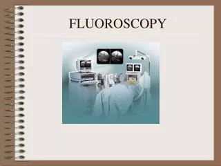
FLUOROSCOPY • Primary function – dynamic motion studies • Motion of internal structures in real time • CONVENTIONAL FLUORO HAS BEEN REPLACED BY IMAGE INTENSIFICAITON • Conv Fluoro – Rad directly observing images on a fluoroscopic screen
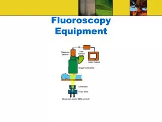
Basic Componets of “old” Fluoroscopy “Imaging Chain” Primary Radiation EXIT Radiation Fluoro TUBE PATIENT 105 Photospot Fiber Optics OR Image Intensifier ABC LENS SPLIT Cassette Image Recording Devices CINE CONTROL UNIT VIDICON Camera Tube TV
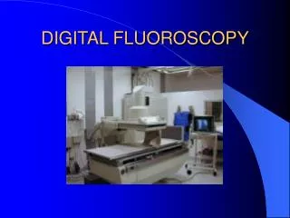
Basic Componets of “NEW DIGITAL” Fluoro“Imaging Chain” Primary Radiation EXIT Radiation Fluoro TUBE PATIENT Analog to Digital Converter ADC Image Intensifier ABC CCD TV
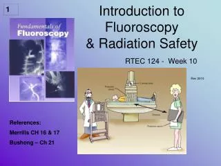
Fluoroscopy: a “see-through” operation with motion • Used to visualize motion of internal fluid, structures • Operator controls activation of tube and position over patient • Early fluoroscopy gave dim image on fluorescent screen • Physician seared in dark room • Modern systems include image intensifier with television screen display and choice of recording devices
Fluoroscopy • X-ray transmitted trough patient • The photographic plate replaced by fluorescent screen • Screen fluoresces under irradiation and gives a life picture • Older systems direct viewing of screen • Nowadays screen part of an Image Intensifier system • Coupled to a television camera • Radiologist can watch the images “live” on TV-monitor; images can be recorded • Fluoroscopy often used to observe digestive tract • Upper GI series, Barium Swallow • Lower GI series Barium Enema
DIRECT FLUOROSCOPY • Early fluoroscopy = the image was viewed directly – the xray photons struck the fluoroscopic screen – emitting light. • The Higher KVP – brighter the light • DISADVANTAGES: • ONLY ONE PERSON CAN VIEW IMAGE • ROOM NEED COMPLETE DARKNESS • PATIENT DOSE (& RADIOLOGIST) WAS VERY HIGH
Direct Fluoroscopy: obsolete In older fluoroscopic examinations radiologist stands behind screen and view the picture Radiologist receives high exposure; despite protective glass, lead shielding in stand, apron and perhaps goggles Main source staff exposure is NOT the patient but direct beam
Conventional Fluoroscopic Unit • Conventional fluoroscopy • User viewed faint image on screen • User in direct path of beam • Very high dose to user and patient • Excellent resolution • No longer used
Older Fluoroscopic Equipment(still in use in some countries) Staff in DIRECT beam Even no protection
Red goggles for dark adaptation More about the eye and vision later in unit………….
Conventional older Fluoroscopy systems 30 min for dark adaptation RODS or CONES VISION?
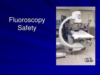
C-arm Under table/over table units Types of Equipment
Raise and lower image receptor for accuracy Can vary beam geometry and image resolution Full beam intercept Types of Equipment
The main components of the fluoroscopy imaging chain • Image Intensifier • Associated image TV system
Basic Componets of “old” Fluoroscopy “Imaging Chain” Primary Radiation EXIT Radiation Fluoro TUBE PATIENT 105 Photospot Image Intensifier Image Recording Devices ABC Cassette Fiber Optics OR CINE CONTROL UNIT VIDICON Camera Tube TV
Basic Componets of “NEW DIGITAL” Fluoro“Imaging Chain” Primary Radiation EXIT Radiation Fluoro TUBE PATIENT Analog to Digital Converter ADC Image Intensifier ABC CCD TV
IMAGE INTENSIFICAITON • IMAGES ARE VIEWED ON A TV SCREEN/MONITOR
THE IMAGING CHAIN Historical maybe– but you have to know this………
Image Intensified Fluoroscopy • Electronic conversion of screen image to light image that can be viewed on a monitor • resolution • dose
FLUORO TUBES CAN BE LOCATED UNDER OR OVER THE TABLE….. FIRST COVERED – UNDER THE TABLE
Different fluoroscopy systems • Remote control systems • Not requiring the presence of medical specialists inside the X Ray room • Mobile C-arms • Mostly used in surgical theatres.