Download
1 / 87
870 likes | 1.04k Views
07 – Bearings and Bushings. The intent of this presentation is to present enough information to provide the reader with a fundamental knowledge of bearings and bushings used within Michelin and to better understand basic system and equipment operations. 07 – Bearings and Bushings.

E N D
The intent of this presentation is to present enough information to provide the reader with a fundamental knowledge of bearings and bushings used within Michelin and to better understand basic system and equipment operations.
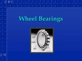
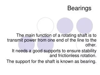
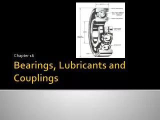
07 – Bearings and Bushings General Information • Bearings and Their Categories • Generalities • A bearing is a mechanical device and it is important to know its various components.
07 – Bearings and Bushings KEY 1) Inner race. 7) Side of inner race. 2) Inner race chamfer. 8) Side of outer race. 3) Inner race track. 9) Cylindrical roller. 4) Outer race track. 10) Cylindrical roller track 5) Outer race. 11) Outer race. 6) Ball. 12) Cage
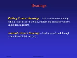
07 – Bearings and Bushings Categories of bearings When in operation, a shaft is subjected to axial and radial forces which tend to push it away from its axis center. Bearings are positioned to resist to these forces and maintain the shaft in proper equilibrium. Manufacturers have grouped bearings under two headings, on the basis of the forces being encountered: radial bearings and axial bearings. Radial bearings Radial bearings are made with balls or rollers, depending on the how the bearings are used. They are designed to withstand forces that are perpendicular to the axis of the shaft.
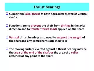
07 – Bearings and Bushings Axial bearings Axial bearings, also known as thrust bearings, have either balls or rollers, but both are designed to withstand axial forces, which push or pull along the axis. The following chart shows different Bearing Identification Codes
bbbbbbbbbbbbbbbbbbbbbbbbbbbbbbbbbbbbbbbbbbbbbbbbbbbbbbbbbbbbbbbbbbbbbbbbbbbbbbbbbbbbbbbbbbbbbbbbbbbbbbbbbbbbbbbbbbbbbbbbbbbbbbbbbbbbbbbbbbbbbbbbbbbbbbbbbbbbbbbbbbbbbbbbbbbbbbbbbbbbbbbbbbbbbbbbbbbbbbbbbbbbbbbbbbbbbbbbbbbbbbbbbbbbbbbbbbbbbbbbbbbbbbbbbbbbbbbbbbbbbbbbbbbbbbbbbbbbbbbbbbbbbbbbbbbbbbbbbbbbbbbbbbbbbbbbbbbbbbbbbbbbbbbbbbbbbbbbbbbbbbbbbbbbbbbbbbbbbbbbbbbbbbbbbbbbbbbbbbbbbbbbbbbbbbbbbbbbbbbbbbbbbbbbbbbbbbbbbbbbbbbbbbbbbbbbbbbbbbbbbbbbbbbbbbbbbbbbbbbbbbbbbbbbbbbbbbbbbbbbbbbbbbbbbbbbbbbbbbbbbbbbbbbbbbbbbbbbbbbbbbbbbbbbbbbbbbbbbbbbbbbbbbbbbbbbbbbbbbbbbbbbbbbbbbbbbbbbbbbbbbbbbbbbbbbbbbbbbbbbbbbbbbbbbbbbbbbbbbbbbbbbbbbbbbbbbbbbbbbbbbbbbbbbbbbbbbbbbbbbbbbbbbbbbbbbbbbbbbbbbbbbbbbbbbbbbbbbbbbbbbbbbbbbbbbbbbbbbbbbbbbbbbbbbbbbbbbbbbbbbbbbbbbbbbbbbbbbbbbbbbbbbbbbbbbbbbbbbbbbbbbbbbbbbbbbbbbbbbbbbbbbbbbbbbbbbbbbbbbbbbbbbbbbbbbbbbbbbbbbbbbbbbbbbbbbbbbbbbbbbbbbbbbbbbbbbbbbbbbbbbbbbbbbbbbbbbbbbbbbbbbbbbbbbbbbbbbbbbbbbbbbbbbbbbbbbbbbbbbbbbbbbbbbbbbbbbbbbbbbbbbbbbbbbbbbbbbbbbbbbbbbbbbbbbbbbbbbbbbbbbbbbbbbbbbbbbbbbbbbbbbbbbbbbbbbbbbbbbbbbbbbbbbbbbbbbbbbbbbbbbbbbbbbbbbbbbbbbbbbbbbbbbbbbbbbbbbbbbbbbbbbbbbbbbbbbbbbbbbbbbbbbbbbbbbbbbbbbbbbbbbbbbbbbbbbbbbbbbbbbbbbbbbbbbbbbbbbbbbbbbbbbbbbbbbbbbbbbbbbbbbbbbbbbbbbbbbbbbbbbbbbbbbbbbbbbbbbbbbbbbbbbbbbbbbbbbbbbbbbbbbbbbbbbbbbbbbbbbbbbbbbbbbbbbbbbbbbbbbbbbbbbbbbbbbbbbbbbbbbbbbbbbbbbbbbbbbbbbbbbbbbbbbbbbbbbbbbbbbbbbbbbbbbbbbbbbbbbbbbbbbbbbbbbbbbbbbbbbbbbbbbbbbbbbbbbbbbbbbbbbbbbbbbbbbbbbbbbbbbbbbbbbbbbbbbbbbbbbbbbbbbbbbbbbbbbbbbbbbbbbbbbbbbbbbbbbbbbbbbbbbbbbbbbbbbbbbbbbbbbbbbbbbbbbbbbbbbbbbbbbbbbbbbbbbbbbbbbbbbbbbbbbbbbbbbbbbbbbbbbbbbbbbbbbbbbbbbbbbbbbbbbbbbbbbbbbbbbbbbbbbbbbbbbbbbbbbbbbbbbbbbbbbbbbbbbbbbbbbbbbbbbbbbbbbbbbbbbbbbbbbbbbbbbbbbbbbbbbbbbbbbbbbbbbbbbbbbbbbbbbbbbbbbbbbbbbbbbbbbbbbbbbbbbbbbbbbbbbbbbbbbbbbbbbbbbbbbbbbbbbbbbbbbbbbbbbbbbbbbbbbbbbbbbbbbbbbbbbbbbbbbbbbbbbbbbbbbbbbbbbbbbbbbbbbbbbbbbbbbbbbbbbbbbbbbbbbbbbbbbbbbbbbbbbbbbbbbbbbbbbbbbbbbbbbbbbbbbbbbbbbbbbbbbbbbbbbbbbbbbbbbbbbbbbbbbbbbbbbbbbbbbbbbbbbbbbbb
07 – Bearings and Bushings In the precision and play (clearance) suffixes, "P" refers to the tolerances of each bearing component and "C" refers to the precision of radial play between the rolling element and the race (track).
07 – Bearings and Bushings Internal Clearance The internal clearance has a direct impact on the tightness of the bearing around the shaft. Therefore, one must replace a bearing by another of the same type with the same dimensions and clearance. Does NOT apply to Conical Bore bearings on adapter sleeves This chart is an example of differences between the various clearance codes. It explains the precision variance pertaining to the radial clearance for an identical bearing, but with a different degree of precision. The normal clearance is the standard manufacturing clearance.
07 – Bearings and Bushings Conversion of values into the imperial system To convert into inches the values shown in microns (SI), simply divided the microns by 25.4. 1 thousandth of an inch = 25.4 microns and 1 micron ‑ 0.001 mm Major Rules of Bearing Maintenance Bearing components have highly‑precise surface finish and shape; therefore they are extremely sensitive to external forces. This is why it is imperative that they always be handled with utmost care. Storing Bearings must remain in their original packing material until installation time. The packing material must be removed only on the installation site and just prior to installation. Bearings must be stored in a dry place, away from the cold. Otherwise, they could gum up and corrode. They must always be stored flat. NOTE: Do not store bearings in any area that also contains corrosive chemicals, such as acid, ammonia or bleaching lime.
07 – Bearings and Bushings • Rules pertaining to the handling of bearings • work with clean and approved tools in a clean environment • handle bearings with clean and dry hands or with clean canvas gloves • work on a metal table or a table covered with metal • carefully handle a used bearing as a new one, until it is clear that the bearing is defective • use clean solvents • put the bearing on a clean surface • protect removed bearings against humidity and dirt • if necessary, wipe the bearing with a clean, lint‑free cloth • keep the bearing in waxed paper when it is not being used • clean the shaft or the housing before installing the bearing • install new bearings right from its packing material; do not wash a bearing that comes out of a sealed container • use only clean lubricating material on a bearing and keep lubricant containers closed when they are not being used
07 – Bearings and Bushings Inspection Once a bearing has been removed, inspect it. First, it needs to be cleaned in a non‑flammable solvent, then dried carefully with a clean, lint‑free cloth or with low‑pressure compressed air (for safety reasons, make sure that no components of the bearing are set in motion). Examine the rings and the rolling components to look for possible deterioration.
07 – Bearings and Bushings Bearings that are protected by joints or flanges must never be cleaned. For obvious reasons, they cannot be inspected. To make sure that the rolling noise is normal, spin the outer ring. • A bearing that has not suffered deterioration, is free of imprints, cracks and flaking, and its rotation is regular, without excessive radial play can be reinstalled without danger.
07 – Bearings and Bushings Single Row Ball Bearing vs. a Plain Bushing Generalities Advantages of a bearing: 1. Reduces friction 2. Axial space requirements are small 3. Reduced maintenance 4. Ease of replacement 5. Prevents wear on the shaft and housing Disadvantages of a bearing: 1. Requires more radial space 2. Less loading over the same I.D. bushing NOTE: When using bearings over bushings, we give up heavy loading for higher RPM’s
07 – Bearings and Bushings Pre-Lubricated Sintered Bronze Bushings (“Oilite”) This Oilite bushing is manufactured using metallurgical powder techniques in order to have a porous material. It takes on the form of a metallic sponge, all the pores of which communicate with each other and the surface. This porosity accounts for 30% of the volume of the part; and it is impregnated with a hydrocarbon oil. • Manufacturing of the bushing • Powder agglomeration: The powders are cold compressed in a mold (copper powders, tin powders, iron powders, etc.). • Sintering: The parts are baked. • Calibration: This is to compensate for the deformation caused during the sintering process. • Impregnation: Oil is forced into the pores in a vacuum.
07 – Bearings and Bushings Fits: Tolerance on the housing: H7 Tolerance on the shaft: f7 or g6
07 – Bearings and Bushings Putting bushings in place Use a perfectly cylindrical polished mandrel. (Once the operation has been completed, give the tools back to the crib having greased them)
07 – Bearings and Bushings Material supplied by the tool crib for installing a bushing with a press Put washer 1 on mandrel 2 Slide the bushing onto the mandrel Push into the part using the press Remember the Fits are: Tolerance on the housing: H7 Tolerance on the shaft: f7 or g6 2 1
07 – Bearings and Bushings • Removal of a mandrel • Mount the extractor upon the fitted assembly. • Turn the screw until the mandrel is completely removed. • Utilization of these bushings: • Low rotational speed • High radial load • No axial movement • No alternating movement • Note: These bushings should be mounted with a mandrel only, and should never be reamed to size, due to the fact that reaming will shear the sintered bronze spheres and the burrs will tend to clog the lubrication passages.
07 – Bearings and Bushings Teflon Impregnated Bronze Bushings (DU Bushing) Definition Different plastics are used for bushings; among these, is polytetrafluorethylene (called P.T.F.E. or Teflon), the most widely used. This type of bushing has the advantage of combining the excellent frictional properties of P.T.F.E. It is not a self-lubricating friction material, for it runs without lubricant. However, no difficulty is caused by the presence of a lubricant which can even often be a positive additive. • Composition • This bushing is composed of three layers: • A support made of sheet steel, tinned to protect it from corrosion. • An intermediary layer of sintered bronze mixed with P.T.F.E. and fine lead powder • A surface layer which is a mixture of Teflon and a fine lead powder, approximately 25 µ meters thick.
07 – Bearings and Bushings • Different parts • Parts made of this combination of materials may be: • rolled bushings • thrust washers • flat strips • Fits • Tolerance on the housing: J7 or H6 • Tolerance on the shaft: h6 or h8
07 – Bearings and Bushings • Fitting of a DU bushing using a press • Lightly grease the outside of the DU bushing • Chamfer the housing • Press bushing into housing Mandrel After using the mandrel carefully grease it and return it to the tool crib. DU Bushing • Note: These bushings are used to meet the following conditions: • Reduced speed • Heavy load • Longitudinal movement • Alternating movement • The bore of these bushings must not be burnished or modified in any other way.
07 – Bearings and Bushings Installation techniques
07 – Bearings and Bushings • Removal of bearings • Great care must be taken when removing a bearing that will be used again. • Preliminaries • Before undertaking the removal of a bearing, the shaft and the bearing housing must be thoroughly cleaned. It also matters that reference points be noted regarding the position of the installed bearing (taking measurements with a ruler, for instance). It is also important to take down the number of the bearing so as to replace it, if necessary, by an identical one, or by an equivalent bearing approved by the company.
07 – Bearings and Bushings • Tools • There are three major families of tools used in removing a bearing: • mechanical extractors or hydraulic rings; • mechanical or hydraulic presses; • hammer and proper support (bushes and pipes). Removal tools Removal Tools Extractors Extractors are tools which help remove bearing through a pulling action.
07 – Bearings and Bushings Mechanical extractors Mechanical extractors use the shaft as a support and their screw to pull away the bearing. Examples of mechanical extractors
07 – Bearings and Bushings Hydraulic extractor The hydraulic extractor is the most powerful extraction system for bearings. Some models can apply a number of tons of pressure. It works by gripping the bearing and then applying pressure on the shaft. NOTE: It is very important to leave the nut on the shaft, but it does need to be loosened by a couple of turns.
07 – Bearings and Bushings Presses Presses are used when one can use the bearing as a support and apply pressure against the shaft to separate it from the bearing. They are usually mounted on a workbench and the pressure is applied mechanically (rack) or hydraulically.
07 – Bearings and Bushings • Hammer and supports • When neither an extractor nor a press will do the job, the bearing can be removed with a hammer. The figure below shows two methods of removal with a hammer. It shows that the impact of the hammer is distributed over the entire surface of the bearing. Please note that the hammer does not strike the shaft directly, but a piece of soft metal is placed against it. • Examples of hammer use • These diagrams show that: • when the bearing is installed on a shaft, support • is taken on the inner ring • when the bearing is lodged in a housing, support • is taken on the outer ring • NOTE: If the bearing held both in a housing and on a ring, one should, if possible, support • simultaneously the inner and outer rings. If this cannot be done, try to support the tighter of the two rings.
07 – Bearings and Bushings Basic technique Removing a bearing is not a complicated operation. The only difficult thing is to avoid damaging it, so that it can be used again. As shown before, the bearing is equipped with an inner ring and an outer ring. Usually, pressure is exerted on only one of the two rings during removal. Therefore, the pressure is applied on the ring where the support is the greatest. Ring support
07 – Bearings and Bushings Installation of bearings In order for a bearing to work properly and last as long as it is intended to last, correct installation methods and the observance of work area cleanliness are of paramount importance. Preliminaries It is important to inspect carefully all components that pertain to the installation; to verify that the shape and dimension of the shaft face and of the housing are exact, since damage may have occurred during removal; to clean the shaft and shoulder; to examine the gaskets and to replace those that are worn or damaged. Tools Special tools have been devised to install bearings.
07 – Bearings and Bushings Various installation bushings There are a variety of installation bushings, depending on the type of bearing. If you do not have the specific bushing that is required to install a particular bearing, it is preferable that one be made. It could prove useful when installing other bearings of the same kind.
07 – Bearings and Bushings Hydraulic presses There are a number of models of hydraulic presses: some are designed specifically for bearing installation, while others have a more widespread use. Annular‑piston presses When a large swivel‑joint roller bearing has to be installed, it is preferable, when adjusting the tightness, to use an annular‑piston press rather than a spanner wrench and a locknut. The work performed with such a press is faster, safer and more precise.
07 – Bearings and Bushings Installation nuts Locknuts equipped with a lock clip as well as lock washers are required installation accessories. The locknut is used to tighten the bearing during the adjustment operation, while the lock washer is used to maintain the tightened locknut in position. Typical designations: KM 4 Nut + MB 4 Washer (metric) KM Nut MB Washer
07 – Bearings and Bushings Tight adjustment on the shaft When a bearing has to be tightly fitted onto the shaft, it is advisable to put a little bit of low-viscosity oil on the shaft face, so as to avoid damaging the shaft during installation. Small bearings can be installed with an installation bushing or a tube. The tube must be clean and have flat and parallel surfaces, as well as right angle ends. Position the tool against the inner ring and strike evenly all around with an ordinary hammer (not one made of lead or other soft metals, because small fragments could chip off). NOTE: Make sure that the bearing is not in an oblique (cocked) position relative to the shaft.
07 – Bearings and Bushings If a mechanical or hydraulic press is available, it can be used for installing small or medium bearings. Bearings are easier to install if they are heated to a temperature of 80 to 120°C (170 to 250°F). Make sure that the temperature does not exceed 120°C. The most appropriate heating method is to use an oil bath. The oil must be clean and have a flash point greater than 250°C. The bearing must not touch the bottom of the container.
07 – Bearings and Bushings NOTE: There is a compound which will ensure that the bearing will not be heated at more than 120°C (cutting oil). The bearing can also be heated by electric flux density. To determine the temperature, one can either use special chalks that melt at given temperatures, or read a thermocouple mounted on the device. • Once the bearing has been heated, a number of precautions need to be taken, namely: • use of clean safety gloves or rags to keep the bearing clean; • removal of oil that could remain in the inner ring or wiping of the bore; • quick positioning of the bearing; • firm hold on the bearing against the shoulder until it has sufficiently cooled.
07 – Bearings and Bushings Tight adjustment into the housing If the bearing needs to be held tightly inside the housing, it is preferable to apply a thin coat of oil on the bearing's surface. An installation bushing or a clean tube must be used (placed against the outer ring). NOTE: Make sure that the bearing is not positioned obliquely (cocked) in the housing. One can also use a mechanical or a hydraulic press. Sometimes, it is necessary to heat the housing to be able to position it. One can use an electric light bulb or hot oil.
07 – Bearings and Bushings Bearings on a sleeve The inner ring of conical bore bearings is always tight fitted, usually on an adapter sleeve or a withdrawal sleeve. Place the adapter sleeve on the shaft at the position noted before removal.
07 – Bearings and Bushings Before positioning the bearing, the radial play must be determined with the blade of a thickness gauge. Just before installation, remove the rust proofing compound from the bearing. Put the bearing and the locknut on the shaft, then tighten the locknut, using the appropriate wrench, so as to affix the bearing around the shaft. The lock washer must be installed only once the proper tightness has been reached.
07 – Bearings and Bushings After this, regularly check the decrease in play during the positioning. The measurement must be made in that segment of the bearing which is not carrying the load. The mechanic will have to follow the recommendations given on the following charts to ensure maximum performance.
07 – Bearings and Bushings For bearing sizes 04 to 96, the diameter on the smaller side of the bore, in millimeters, corresponds to five times the size number. For bearing sizes 500 and above, the size number corresponds to the bore diameter on the smaller side of the tapered bore Example: Bearing 22244CCK/C3W33 (bore diameter of 220 mm) to be installed on conical shaft. Measure the initial play using calibrated blades. The above chart shows that the initial play will be between 0.250 and 0.320 mm. Using a locknut (or other equivalent means), push the bearing on its conical shaft until the play is brought down to the value shown in the following chart
07 – Bearings and Bushings Bearing Failures
07 – Bearings and Bushings • Main Causes Of Bearing Failure And Stoppages • Causes • Premature failure is generally caused by one or more of the following: • contamination • misalignment • incorrect lubrication • flow of an electric current through the bearing • Distortion • incorrect adjustment • vibration when the bearing is not in motion • poor maintenance practices.
07 – Bearings and Bushings Contamination Contamination is defined as any foreign substance causing damage to the bearing. Humidity or an abrasive, such as sand or dust, will cause premature failure. The figure to the right shows scratches caused by grains of sand (a) and rust caused by humidity (b).This kind of failure can be avoided by using the appropriate lubricant, by keeping the bearing clean during handling and by using seals that are clean and free of damage.
07 – Bearings and Bushings Distortion When the shaft or the housing has been distorted, the bearing can wear out faster. If the shaft or the housing is no longer round, the rolling parts of the bearing will be subjected to extra pressure where the shaft or the housing is too large. This will cause cavities on the running surface. This problem can be solved by correcting the shaft or the housing. If neither can be repaired, the defective parts will have to be replaced.
07 – Bearings and Bushings Misalignment Misalignment can be caused by a shaft that has been twisted, by shoulders that are not square, by a housing that is not parallel or by foreign objects caught between the bearing and its support. The figure to the right shows the classic consequence of misalignment: notice the path that the balls follow. The cause of such misalignment must be determined and corrected, otherwise the same problem will appear with the new bearing.
07 – Bearings and Bushings Incorrect adjustment The figure to the left shows a failure caused by an incorrect alignment. The example shows that the inner ring is broken; this is the result of forcing a bearing onto a shaft that is too large.