Download
1 / 13
130 likes | 305 Views
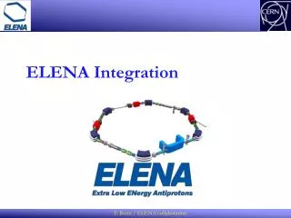
ELENA KICKERS AND SEPTA. ELENA Meeting, 28.09.2011 Prepared by J. Borburgh, E. C arlier, A . Fowler, L . Sermeus TE/ABT. Contents. Introduction: TE/ABT equipment Septa Kickers. TE/ABT equipment. ELENA (new) 2 septa 2 (+1 foreseen) kickers. ELENA Ring. AD (existing)

E N D
ELENA KICKERS AND SEPTA ELENA Meeting, 28.09.2011 Prepared by J. Borburgh, E. Carlier, A. Fowler, L. Sermeus TE/ABT
Contents • Introduction: TE/ABT equipment • Septa • Kickers L. Sermeus
TE/ABT equipment • ELENA (new) • 2 septa • 2 (+1 foreseen) kickers ELENA Ring • AD (existing) • 8 kicker systems • 2 septa L. Sermeus
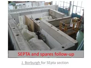
Septa What’s already available? L. Sermeus
Septa What’s needed? • Mechanical support • Water cooling manifold gauges, flow meters, filters and valves • Magnet protection interlock system What’s needed, but not included? • Vacuum chambers (TE/VSC?) • Power supplies (TE/EPC?) L. Sermeus
Septa Resource requirements and what can collaborations contribute to? L. Sermeus
Kickers ELENA and AD kicker system layout Features: • SF6 Gas filled Pulse Forming Line • PFL voltage up to 80 kV • Thyratronswitches • use of oil for cooling and insulation 10 systems: 2 for ELENA and 8 for AD (+space for 2 new spares for future needs like second Elena extraction line) L. Sermeus
Kicker generators relocation Option 3 second most preferred to be studied Option 2 most preferred but technically difficult and exposed to radiations Option 4 least preferred (above racks) Present kicker platform (10 generators) Option 1 least preferred (space needed for future experiences) L. Sermeus
Kicker magnets and tanks Basic assumption: use of existing unused AC ejection or AA injection magnet modules (to be confirmed by P. Belochitskii) • 3D models of magnets to be made with Catia software. • Two new magnet frames made of stainless steel to be manufactured for 300 °C bake-out.(ex AC magnets only) • Magnets to be dismounted and reassembled with new frame. (ex AC magnets only) • Two (identical ?) 300 °C bake-able vacuum tanks and ancillaries to be designed, manufactured, equipped and tested. AA magnet AC magnet L. Sermeus
Kicker magnets and tanks Resource requirements and what can collaborations contribute to? (*) without controls L. Sermeus
Kicker platform displacement Resource requirements and what can collaborations contribute to? (the cost and manpower for a new building are not included) (*) without controls L. Sermeus
Kicker controls Resource requirements and what can collaborations contribute to? L. Sermeus
Conclusion • TE/ABT related work and resource needs have been presented. • Critical points are still to be clarified: • final choice of extraction kicker magnet • new location of the kicker platform Reference: CERN-BE-2010-029 OP, November 2010 L. Sermeus