Download

1 / 38
380 likes | 532 Views
11022 Transcutaneous Signal Transmission for LVAD. November 5 , 2010 Yevgeniy Popovskiy, Vince Antonicelli, Craig LaMendola , Chrystal Andreozzi. Detailed Design Review. Determine if our T eam is on Track New Ideas Meeting Customer Needs To Ensure our Proposed Solution is Feasible

E N D
11022 Transcutaneous Signal Transmission for LVAD November 5 , 2010 Yevgeniy Popovskiy, Vince Antonicelli, Craig LaMendola , Chrystal Andreozzi
Detailed Design Review Determine if our Team is on Track New Ideas Meeting Customer Needs To Ensure our Proposed Solution is Feasible To Ensure that our Team has Developed that Ideal Solution to the Problem at Hand
Detailed Design Review Agenda • Project Summary • Customer Needs • Engineering Specifications • Schedule • Project 10022 Failures • High Level Schematics • Electrical Detailed Design • Case Design • Heat Transfer Analysis • Cable Design • Bill of Material • Test Plan • Questions, Concerns, Ideas • Action Items Review
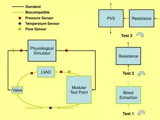
Project Background The Left Ventricular Assist Device (LVAD) is a electro mechanical circulatory device designed to assist a patient with a failing heart. Typically, a patient will receive one for temporary use after a heart attack or major heat surgery. Eliminate as many transcutaneous wires as possible running from the external battery and controller to the LVAD.
Customer Needs and Engineering Specifications THE SYSTEM NEEDS TO WORK!!!! • Must Operate Reliably for 6 hours • Cable Size Reduced to 3mm • Improve Cable Flexibility by 200% • Internal Volume must be less then 450 cm3 The device must be reliable The number of wires needs to be reduced The cable diameter needs to be reduced The cable needs to be more flexible Meet FDA standards
Big Picture External Case “Big Black Box” ICs Internal Case Skin LVAD ICs Motor Controller Amplifiers
Electronics Function The Big Black Box SKIN 3 1 2 SA Sensors MCC + MCT Motor Controller Amplifiers PAAS=>PADS
Current Schematic Skin SA (Sensor Analog) Pump 8 Wires SP (Sensor Power) Main Controller+ A/D + Battery MCC 2 Wires MCO Blood Pump (Mot. Cont. Control) (Mot. Cont. Out) Motor Control 2 Wires MCP 2 Wires (Mot. Cont. Pwr) 2 Wires LAOP LADS (Linear Amplifier Output) (Linear Amplifier Input) 4 Wires 4 Wires Linear Amplifier LAP LAOG (Linear Amplifier Power) (Linear Amplifier Output Return) 2Wires 1Wires
Project 11022 Schematic Skin NSD SA (New Signal Digital) (Sensor Analog) SA (Sensor Analog) 8 Wires SP 8 Wires 3 Wires (Sensor Power) Chip + Elect. 2 Wires Chip + Elect. MCC Main Controller+ A/D MCO MCC Motor Control (Mot. Cont. Cont) Blood Pump MCP 2 Wires (Mot. Cont. Control) (Mot. Cont. Out) (Mot. Cont. Pwr) 2 Wires PAAS PADS (PWM Analog Signal) 4 Wires PWM Gen. 4 Wires (PWM Signal) PAOP PAP+MCP+SP (PWM Output) (PWM Mot Cont Sen Pwr) PAP 8 Wires 2 Wires (PWM AMPLIFIER POWER)
Electronic Details External Internal 1 3 2 SKIN CLR DAC SA SA ADC MUX MUX INIT LOGIC MCT MCT FLIP FLOP MCC POR MCC INIT LOGIC PAAS ADC DN CNT PADS COUNTER COUNTER
Internal Case *Design not finalized • Main Compartment: 5.25” x 2.25” x 1.25” • Second Compartment: 4.5” x 2.15” x 0.5” • Outer Dimensions: 6.63” x 2.63” x 2.25” Titanium 2 shielded compartments 3 piece design with 2 equally sized halves and shielding plate Main compartment to hold electronics provided by Customer Second smaller compartment to house our new electronics
External Case *Design not finalized Case Similarities • Cord grips screw into case • Same 1/16” O-ring • Same square O-ring grooves • Sharp corners and edges eliminated • Adhesive board and cable mounts • Board will be grounded to case • Will be quoted by multiple local shops Aluminum One compartment Will accommodate 2” x 2” x 0.5” board Outer Dim. 2.37” x 3.13” x 0.87”
Hardware on Cases • Cord Grips: Sealcon products • Pressure tested • O-rings: Silicone 1/16” McMaster • Additional sealing: • Loctite silicone sealant on O-ring seal • Water tight thread tape on cord grip threads, in addition to stock O-ring • Screws: All Stainless Steel from McMaster • No lead time problems expected on Hardware
Cable • Reduce Cable Diameter • Flexibility: the ability to bend a cable through its full-range of required motion • Bend Radius: is the minimum inside radius one can bend a cable • Stiffness: is the resistance of elastic body to deformation by an applied force along a given degree of freedom
3 mm 22 Gage, 6 A 1 mm 22 Gage, 6 A 1 mm Cable Copper Shielding Heat Shrink Tubing Thickness 0.38 mm 36 Gage, 0 A 0.3 mm
Cable Choices • Make cable at RIT • Custom cable Manufactures • Coast Wire & Plastic Tech., Inc. • Calmont Wire & Cable • Merit Cable • Carroi’s Medical Cable • American Biosurgical
Test Plan • LVAD Simulation Signal Test • Electronics Functionality Test • Leak and Pressure Test • Drop Test • Heat Transfer Test • Flexibility Testing • Bend Radius • Stiffness
LVAD Simulation Signal Test Before connecting to LVAD and Dr. Days Equipment we will be preforming a simulation by monitoring the signals coming in and out using Function Generator and Oscilloscope.
Electronics Functionality Test • They System Must operate Continuously for 6 hours. • Test: • 3 one hour test • 3 one hour test in Water(dependent on leak test) • 1 six hour test
Leak and Pressure Test • Test fully assembled cases with no electronics inside • O-rings will be installed with Loctite silicon sealant • Place cases in water 1 meter deep for 15 minutes • Case will experience 10 kPa of pressure • Cases will contain a test material to absorb water • Cases will be opened up to ensure success
Drop Test • Test fully assembled cases with no electronics inside • Cases will be dropped from height of 1.5 meters • Internal case will be dropped onto carpet to protect surface from marking • External case will be dropped onto concrete to simulate worst case scenario • We will inspect the cases to ensure full structural integrity was maintained • Secondary leak test
Heat Transfer Test For feasibility reasons will be preforming the test in Water
Cable δ= Deflection Flexibility Test: Stiffness Spring Scale C-Clamp Applied Force Determine the Stiffness of the individual cables by apply 3 different applied Force.