Download
1 / 45
460 likes | 658 Views
Yagi Antenna Design for Animal Tracking Applications. Minh Phan, Andrew Price, Denny Tu University of Illinois at Urbana-Champaign Department of Electrical Engineering Senior Design, ECE345 May 2, 2003. Motivation for Project.

E N D
Yagi Antenna Design for Animal Tracking Applications Minh Phan, Andrew Price, Denny Tu University of Illinois at Urbana-Champaign Department of Electrical Engineering Senior Design, ECE345 May 2, 2003
Motivation for Project The current method used to track tagged animals requires scientists to manually drive around with portable antennas tracking the particular animal(s) they are interested in. This method is very time consuming and produces small amounts of data. In order to facilitate an automatic tracking system, antennas to receive the signals from the tags must be designed, built and tested.
Whole System Overview Antenna 1 RF switch matrix Antenna 6 Data Display Signal Processing Filters Amplifiers (this project only involves the dashed part)
Objectives • Design a yagi antenna using simulation software. • Build the antenna according to designed specifications. • Test antenna and verify it performs as expected. • Design an RF switch matrix to switch 6 antenna feed lines to 1 or 2 amplifiers in the down conversion module.
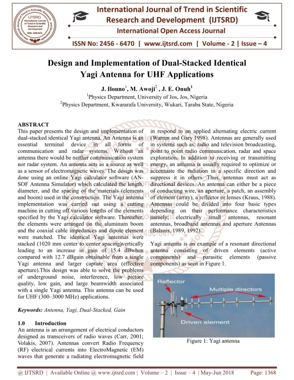
The Yagi Antenna • Invented in the 1920s by Hidetsugu Yagi and Shintaro Uda, two Japanese university professors • A type of multielement array
Components of a Yagi • Center boom • Can be metallic, but requires correction to elements
Components of a Yagi • One driven element • Connected to source • Only active element
Components of a Yagi • One reflector • Positioned behind the driven element • Reflects radiation in desired direction
Components of a Yagi • N ≥ 0 directors • Placed in front of driven element • Directs radiation in desired direction • Focuses radiation pattern
Components of a Yagi • Matching device • Matches impedance of antenna to a desired value • T match • Matches impedance of antenna to 50Ω • Balanced matching device • Reduces pattern distortion
Components of a Yagi • Balun • Connects BALanced antenna to UNbalanced coax • Prevents common-mode currents on the outer surface of the outer conductor of the coax feed which can affect the pattern and other properties • Can also perform an impedance transformation
Components of a Yagi • 1:1 balun
How a Yagi Works • Driven element radiates • Radiation induces currents in reflector and directors • These currents in turn re-radiate • Adjusting the length of elements, their diameters and relative positions along the boom adjusts the radiated fields
How a Yagi Works • The previously mentioned parameters are adjusted in such a way as to make the fields constructively interfere in one direction, and destructively interfere in the opposite direction • This creates the typical directional radiation pattern
Design Requirements • Half-power beam width ≈ 60° • In order to ensure adequate coverage of areas between antennas • As large a gain as possible • As large a front-to-back ratio as possible • Connect to a 50Ω coax cable
Yagi Design • Used Quickyagi to design antenna • Used Yagicad to determine matching parameters
Yagi Design • E plane field
Yagi Design • H plane field
Yagi Design • A conducting boom will be used to build the antenna, so a correction to the lengths of the elements is required to prevent pattern distortions • Boom diameter = 1.25” ≈ .032 λ • Correction ≈ 29%*1.25” ≈ 9mm Percent of Boom Diameter Which Must be Added to Element Length
Yagi Construction • Materials • Boom • 6’ long aluminum tube • 1.25” outer diameter • Elements • 3/16” diameter aluminum (copper for driven element) rods • Plastic insulators and push-nut retaining rings to attach elements to boom
Yagi Construction • Holes in boom drilled by computer controlled machine in the ECE machine shop • Elements cut using band saw in ECE machine shop • T-match bars and balun soldered on
Antenna-Network Analyzer (NA) • First step One port (port1) calibrate by use SOLT (short, open, load, and through) standard kit. So port 1 will be connect to Yagi antenna. • From NA we should see at corrected calibration by display Smitch chart such as Open, short, and load located as where it should be. • The frequency range from 100mhz to 1Ghz
Example show standard kit • Using a coax cable 50 ohms hookup with a adapter then we connected each of components as disired from stanadard kit short, open, and load. Let take a look at the Load
Connect through NA • Port1 have been done calibrate then connect yagi antenna at this time we will try get it match 50 ohms. • Port2 connect monopole with coax cable 50 ohms
Monopole Antenna - Purpose • Not in our original plan. • For testing, needed constant transmitter for yagi antenna to receive signal. • Difficult to find/use natural transmitters operating at 302MHz (band of our yagi is narrow). • Can use easily in lab.
Monopole Antenna - Transmitter • Extended center conductor of a coax cable of length λ/4 ≈ 25cm to transmit at 302 MHz • Ground plane: aluminum foil covered cardboard base • Ground plane: 50cm x 50cm, equidistant from center conductor on all sides • Copper tape to connect outer conductor of coaxial cable to ground plane
Testing – Impedance Background • Ideal: 50 ohms real, 0 ohms reactance • Impedance Matching is what the calibration was needed for. • Theory T Match: use 0.2m copper wire, arm length 2.7cm, spacing 2.1cm, capacitance 16pF
Testing – Impedance Procedure • 1. Connect antenna port1 • 2. Direct antenna facing out open lab window in order to minimize reflection (accuracy) • 3. Read impedance using Smith Chart and marker at 302MHz • 4. Adjust connectors, test different lengths
Testing – Impedance Procedure2 • 5. Couldn’t achieve close to desired impedance. • 6. Hypothesis: Balun may be at fault, so remove it. • 7. More testing, still no positive results. • 8. Get additional wire, according to theoretical predictions. • 9. Silver wire very difficult to solder. • 10. Test T-Match and Gamma-Match, still not desired results. • 11. Replace with 14mm copper wire, bend, test. • 12. Discover wiring incorrect. • 13. Correct wiring and attach balun once more because needed to match currents.
Testing – Impedance Procedure3 • 14. More testing and adjusting, Gamma-Match, T-Match • 15. Recheck and redo the solder connections • 16. Adjust height, distance, angle, etc. • Finally, achieve results close to ideal goal: • 51.1 real, 2.3 reactance, 97.5 % get through • 47.5 real, -13.5 reactance, 86 % get through
Testing – Impedance SWR • Standing Wave Ratio near 1 demonstrates matching working well (very little reflected): • SWR Formula: |r| = (SWR-1)/(SWR+1)
Antenna – Power Reflection (Log Scale) • Spike at 302 MHz – desired • Spike larger than -10 dB • No other major spikes • Works according to design
Testing – Radiation Tests • Calibration not essential, normalize • H-plane is horizontal, E-plane vertical • Direction of poles have to align • Minimum distance 1-2m between transmitter and receiver • Radiation pattern ideally symmetric • 2 Procedures: • Keep Yagi receiver stationary and rotate monopole transmitter around it at set degree intervals • Keep monopole stationary and turn the Yagi in a circle
Testing – Radiation Procedure1 • 1. Connect monopole to port2 • 2. Keep Yagi stationary on top of 2 chair backs – step back so human body doesn’t adversely affect results. • 3. Hold monopole as far away as possible. • 4. Starting at 0 degrees, take measurements and proceed in 10 degree increments up to 180 degrees. • 5. Keep monopole level with Yagi. • 6. Plot points in Matlab and compare with ideal results obtained from simulation. • 7. Repeat several times for accuracy.
Testing – Radiation Procedure2 • 1. Locate monopole antenna next to window (minimize reflection) and keep stationary. • 2. Set Yagi on chair backs facing the monopole. • 3. Keep monopole and Yagi level. • 4. Take measurements starting at 0 degrees and going to 180 degrees. • 5. After each measurement, turn Yagi antenna 10 degrees, make stationary, step away. • 6. Repeat several times. • 7. Analyze results.
Testing – Radiation Procedure3 • Test if height of monopole relative to Yagi affects results: • Conclusion: not significantly. • Test if distance of monopole relative to Yagi affects results: • Conclusion: beyond 1 meter, it seems to stay the same.
Testing – Results Power Spectrum • Spike at 302 MHz, as designed. • No other comparable spikes. • Worked as expected
Testing – Results Radiation Pattern • Similar to ideal results simulated using computer software • Front to Back Ratio: -30.6 dB/-39.1 dB • Graph shows front half of radiation pattern:
Testing – Results Radiation Pattern 2 • 0 degree to 180 degree sweep. • Somewhat different from expected results but general shape similar. • Discrepancies attributed to non-ideal testing conditions and reflections.
Obstacles and Challenges 1 • Graduate Student Advisor departed • The person we worked most with and assisted us with direction and guidance. • Switch Matrix • Part of original plan – take input from 6 antennas, switching between all 6 within 15ms so as to not miss any data. Produce 1 output that computer program others working on “decodes” to find location of animals. • Many fruitless hours searching and planning. • Ideas that wouldn’t work, didn’t match the specific project specifications and functions. • Professor George Swenson said too difficult for us to do in our meeting with him.
Obstacles and Challenges 2 • Suitable Testing Environment: • Ideal: isolated, open area without conflicting signals but with necessary equipment and accessibility. • Antenna testing lab on top floor of Everitt unsuitable for our antenna bandwidth. • ECE345 Lab turned out to be most viable option but many people working around us = disruptions, conflicting signals, reflections, human interference.
Obstacles and Challenges 3 • Calibration • Only one calibration set found and needed someone to calibrate for us since owner of calibration set didn’t want to leave it with us. • Unable to save calibration so another group using or turning off network analyzer means we need to calibrate again. • Owner of calibration set not always available and we couldn’t proceed without it.
Obstacles and Challenges 4 • Impedance Matching • Very unstable, the slightest touch makes a big change. • Varies a great deal – sometimes one location gives a value, another time the same location gives a totally different value. • Human touch/proximity affects results significantly. • Miscellaneous • Faulty cables • Find sufficient cables and connectors to be able to test using a single network analyzer while maintaining sufficient distance between Yagi and monopole.
Acknowledgements • ECE Professor Bernhard • ECE Graduate student Brian Herting • Professor Larkin of the INHS • 345 TA Chirantan Mukhopadhyay • ECE Professor George Swenson