Download
1 / 61
1.14k likes | 2.08k Views
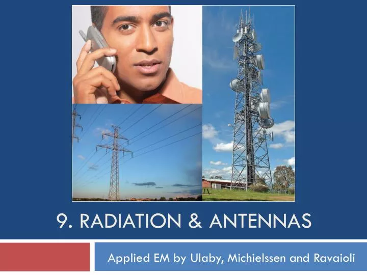
9. Radiation & Antennas. Applied EM by Ulaby, Michielssen and Ravaioli. Overview. Examples of Antennas. Antenna Properties.

E N D
9. Radiation & Antennas Applied EM by Ulaby, Michielssen and Ravaioli
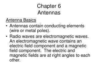
Antenna Properties 1. An antenna is a transducerthat converts a guided wave propagating on a transmission line into an electromagnetic wave propagating in an unbounded medium (usually free space), or vice versa. 2. Most antennas are reciprocal devices, exhibiting the same radiation pattern for transmission as for reception. 3. Being a reciprocal device, an antenna, when operating in the receiving mode, can extract from an incident wave only that component of the wave whose electric field matches the antenna polarization state.
Far-Field Approximation 1. In close proximity to a radiating source, the wave is spherical in shape, but at a far distance, it becomes approximately a plane wave as seen by a receiving antenna. 2. The far-field approximation simplifies the math. 3. The distance beyond which the far-field approximation is valid is called the far-field range (will be defined later).
The Hertzian Dipole A Hertzian dipole is a thin, linear conductor whose length l is very short compared with the wavelength λ; l should not exceed λ/50. This restriction allows us to treat the current along the length of the conductor as constant, even though it has to decay to zero at the ends of the wire.
Fields Radiated by Hertzian Dipole Current along dipole: Magnetic Vector Potential: With: Given A, we can determine E and H
Fields Radiated by Hertzian Dipole (cont.) Upon converting z to spherical coordinates: we have:
Fields Radiated by Hertzian Dipole (cont.) Application of: leads to:
Hertzian Dipole—Far-Field Approximation At any range R: At
Normalized Radiation Intensity Electric and Magnetic Fields Normalized Radiation Intensity Average Power Density
Antenna Radiation Characteristics 1. By virtue of reciprocity, a receiving antenna has the same directional antenna pattern as the pattern that it exhibits when operated in the transmission mode. 2. Total Radiated Power Differential area Solid Angle Power radiated through dA Total Radiated Power
Example of 3-D Pattern F (dB) = 10 log F Principal planes: 1. Elevation plane (x-z and y-z planes) 2. Azimuth plane (x-y plane)
Beam Dimensions 1. Pattern solid angle 2. Half-power beamwidth Since 0.5 corresponds to ‒3 dB, the half power beamwidth is also called the 3-dB beamwidth.
Antenna Directivity D Antenna pattern solid angle Directivity
Antennas with Single Main Lobe Equivalent Solid Angle
Radiation Efficiency and Gain Radiation efficiency Antenna gain G
Example 9-3 (cont.) For any antenna: For the Hertzian dipole:
Half-Wave Dipole 1. Current in half-wave dipole 2. For Hertzian dipole of length l, E field is: 3. Each length element dz of half-wave dipole is like a Hertzian dipole, radiating a field 4. For the entire dipole, the total radiated field is
Half-Wave Dipole (cont.) Integration leads to:
Radiation Pattern of Half-Wave Dipole Radiation pattern resembles that of the Hertzian dipole. Its beamwidth is slightly narrower, 78 degrees compared with 90 degrees for the Hertzian dipole.
Other Half-Wave Dipole Properties 1. Directivity 2. Radiation Resistance This is very important, because it makes it easy to match the antenna to a 75-Ω transmission line. In contrast, the radiation resistance of a dipole whose length is much shorter than a wavelength is on the order of 1 Ω or less. Numerical integration gives:
Quarter-Wave Monopole When placed over a conducting ground plane, a quarter-wave monopole antenna excited by a source at its base [Fig.9-15(a)] exhibits the same radiation pattern in the region above the ground plane as a half-wave dipole in free space. However, its radiation resistance if only half of that of a half-wave dipole, namely 36.5 Ω.
Radiation by Aperture Antennas Instead of calculating the radiated fields E and H at Q due to currents in the antenna, with apertures it is also possible to relate the radiated fields to the electric field distribution across the aperture.
Examples of Aperture Sources • Computational Approaches • a. Vector Formulation--accurate, but mathematically involved • b. Scalar Formulation—easier to implement but restricted to large aperture dimensions (relative to the wavelength) • 2. Both methods are applicable at all wavelengths, including the visible spectrum • 3. Validity of Scalar Formulation. The key requirement for the validity of the scalar formulation is that the antenna aperture be at least several wavelengths long along each of its principal dimensions. • We will limit our treatment to the scalar formulation.
Relating Radiated Field to Aperture Distribution Far Field Condition Radiated E Field Aperture Distribution
Rectangular Aperture with Uniform Distribution Uniform distribution across aperture Scalar formulation leads to: The sinc function is maximum when its argument is zero; sinc(0) = 1.
Examples of Radiation Patterns Circular aperture has circular beam In each principal plane, beamwidth is inversely proportional to antenna dimension in that plane Cylindrical reflector has narrow beam along length direction and wide beam along its width direction
Antenna Arrays An antenna array to a continuous aperture is analogous to digital data to analog. By controlling the signals fed into individual array elements, the pattern can be shaped to suit the desired application. Also, through the use of electronically controlled solid-state phase shifters, the beam direction of the antenna array can be steered electronically by controlling the relative phases of the array elements. This flexibility of the array antenna has led to numerous applications, including electronic steering and multiple-beam generation.
Array Pattern Power density radiated by the entire array Power density radiated by an individual element Array Factor The array factor represents the far-field radiation intensity of the N elements, had the elements been isotropic radiators.