Download
1 / 42
420 likes | 427 Views
Learn about the conditions for interference of light waves, how to combine waves to produce resultant waves, and how to predict the location of interference fringes using the double-slit interference equation. Also, explore the demonstration of interference through narrow parallel slits and the calculation of path difference for interference fringes.

E N D
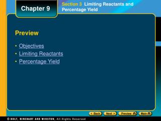
Chapter 15 Section 1 Interference Preview • Objectives • Combining Light Waves • Demonstrating Interference • Sample Problem
Chapter 15 Section 1 Interference Objectives • Describehow light waves interfere with each other to produce bright and dark fringes. • Identifythe conditions required for interference to occur. • Predictthe location of interference fringes using the equation for double-slit interference.
Chapter 15 Section 1 Interference Combining Light Waves • Interference takes place only between waves with the same wavelength. A light source that has a single wavelength is called monochromatic. • Inconstructive interference,component waves combine to form a resultant wave with the same wavelength but with an amplitude that is greater than the either of the individual component waves. • In the case ofdestructive interference,the resultant amplitude is less than the amplitude of the larger component wave.
Chapter 15 Section 1 Interference Interference Between Transverse Waves
Chapter 15 Section 1 Interference Combining Light Waves, continued • Waves must have a constant phase difference for interference to be observed. • Coherenceis the correlation between the phases of two or more waves. • Sources of light for which the phase difference is constant are said to be coherent. • Sources of light for which the phase difference is not constant are said to be incoherent.
Chapter 15 Section 1 Interference Combining Light Waves Click below to watch the Visual Concept. Visual Concept
Chapter 15 Section 1 Interference Demonstrating Interference • Interference can be demonstrated by passing light through two narrow parallel slits. • If monochromatic light is used, the light from the two slits produces a series of bright and dark parallel bands, orfringes,on a viewing screen.
Chapter 15 Section 1 Interference Conditions for Interference of Light Waves
Chapter 15 Section 1 Interference Demonstrating Interference, continued • The location of interference fringes can be predicted. • Thepath differenceis the difference in the distance traveled by two beams when they are scattered in the same direction from different points. • The path difference equals dsin.
Chapter 15 Section 1 Interference Interference Arising from Two Slits Click below to watch the Visual Concept. Visual Concept
Chapter 15 Section 1 Interference Demonstrating Interference, continued • The number assigned to interference fringes with respect to the central bright fringe is called the order number.The order number is represented by the symbol m. • The central bright fringe at q = 0 (m = 0) is called thezeroth-order maximum,or thecentral maximum. • The first maximum on either side of the central maximum (m = 1) is called thefirst-order maximum.
Chapter 15 Section 1 Interference Demonstrating Interference, continued • Equation for constructive interference d sin = ±m m = 0, 1, 2, 3, … The path difference between two waves = an integer multiple of the wavelength • Equation for destructive interference d sin = ±(m + 1/2) m = 0, 1, 2, 3, … The path difference between two waves = an odd number of half wavelength
Chapter 15 Section 1 Interference Sample Problem Interference The distance between the two slits is 0.030 mm. The second-order bright fringe (m = 2) is measured on a viewing screen at an angle of 2.15º from the central maximum. Determine the wavelength of the light.
Chapter 15 Section 1 Interference Sample Problem, continued Interference 1. Define Given:d = 3.0 10–5 m m = 2 = 2.15º Unknown:= ? Diagram:
Chapter 15 Section 1 Interference Sample Problem, continued Interference 2. Plan Choose an equation or situation: Use the equation for constructive interference. d sin = m Rearrange the equation to isolate the unknown:
Chapter 15 Section 1 Interference Sample Problem, continued Interference 3. Calculate Substitute the values into the equation and solve:
Chapter 15 Section 1 Interference Sample Problem, continued Interference 4. Evaluate This wavelength of light is in the visible spectrum. The wavelength corresponds to light of a yellow-green color.
Chapter 15 Section 2 Diffraction Preview • Objectives • The Bending of Light Waves • Diffraction Gratings • Sample Problem • Diffraction and Instrument Resolution
Chapter 15 Section 2 Diffraction Objectives • Describehow light waves bend around obstacles and produce bright and dark fringes. • Calculatethe positions of fringes for a diffraction grating. • Describehow diffraction determines an optical instrument’s ability to resolve images.
Chapter 15 Section 2 Diffraction The Bending of Light Waves • Diffraction isa change in the direction of a wave when the wave encounters an obstacle, an opening, or an edge. • Light waves form adiffraction patternby passing around an obstacle or bending through a slit and interfering with each other. • Wavelets (as in Huygens’ principle) in a wave front interfere with each other.
Chapter 15 Section 2 Diffraction Destructive Interference in Single-Slit Diffraction
Chapter 15 Section 2 Diffraction The Bending of Light Waves, continued • In a diffraction pattern, the central maximum is twice as wide as the secondary maxima. • Light diffracted by an obstacle also produces a pattern.
Chapter 15 Section 2 Diffraction Diffraction Gratings • A diffraction grating uses diffraction and interference to disperse light into its component colors. • The position of a maximum depends on the separation of the slits in the grating, d, the order of the maximum m,, and the wavelength of the light, . d sin = ±m m = 0, 1, 2, 3, …
Chapter 15 Section 2 Diffraction Constructive Interference by a Diffraction Grating
Chapter 15 Section 2 Diffraction Sample Problem Diffraction Gratings Monochromatic light from a helium-neon laser ( = 632.8 nm) shines at a right angle to the surface of a diffraction grating that contains 150 500 lines/m. Find the angles at which one would observe the first-order and second-order maxima.
Chapter 15 Section 2 Diffraction Sample Problem, continued Diffraction Gratings • Define Given:= 632.8 nm = 6.328 10–7 m m = 1 and 2 Unknown:1 = ? 2 = ?
Chapter 15 Section 2 Diffraction Sample Problem, continued Diffraction Gratings • Define, continued Diagram:
Chapter 15 Section 2 Diffraction Sample Problem, continued Diffraction Gratings 2. Plan Choose an equation or situation: Use the equation for a diffraction grating. d sin = ±m Rearrange the equation to isolate the unknown:
Chapter 15 Section 2 Diffraction Sample Problem, continued Diffraction Gratings 3. Calculate Substitute the values into the equation and solve: For the first-order maximum, m = 1:
Chapter 15 Section 2 Diffraction Sample Problem, continued Diffraction Gratings 3. Calculate, continued For m = 2:
Chapter 15 Section 2 Diffraction Sample Problem, continued Diffraction Gratings 4. Evaluate The second-order maximum is spread slightly more than twice as far from the center as the first-order maximum. This diffraction grating does not have high dispersion, and it can produce spectral lines up to the tenth-order maxima (where sin = 0.9524).
Chapter 15 Section 2 Diffraction Function of a Spectrometer Click below to watch the Visual Concept. Visual Concept
Chapter 15 Section 2 Diffraction Diffraction and Instrument Resolution • The ability of an optical system to distinguish between closely spaced objects is limited by the wave nature of light. • Resolving power is the ability of an optical instrument to form separate images of two objects that are close together. • Resolution depends on wavelength and aperture width. For a circular aperture of diameter D:
Chapter 15 Section 2 Diffraction Resolution of Two Light Sources
Chapter 15 Section 3 Lasers Preview • Objectives • Lasers and Coherence • Applications of Lasers
Chapter 15 Section 3 Lasers Objectives • Describethe properties of laser light. • Explainhow laser light has particular advantages in certain applications.
Chapter 15 Section 3 Lasers Lasers and Coherence • Alaseris a device that produces coherent light at a single wavelength. • The word laser is an acronym of “light amplification by stimulated emission of radiation.” • Lasers transform other forms of energy into coherent light.
Chapter 15 Section 3 Lasers Comparing Incoherent and Coherent Light Click below to watch the Visual Concept. Visual Concept
Chapter 15 Section 3 Lasers Laser Click below to watch the Visual Concept. Visual Concept
Chapter 15 Section 3 Lasers Applications of Lasers • Lasers are used to measure distances with great precision. • Compact disc and DVD players use lasers to read digital data on these discs. • Lasers have many applications in medicine. • Eye surgery • Tumor removal • Scar removal
Chapter 15 Section 3 Lasers Components of a Compact Disc Player
Chapter 15 Section 3 Lasers Incoherent and Coherent Light