Download
1 / 11
110 likes | 202 Views
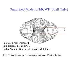
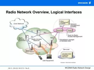
Overview of MCWF Interfaces. The interface configuration is nearing finalization. C-C inner legs are electrically insulated & left to slide ( motion ~0.5 mm). 1 of 3 identical field periods. 5 welds/period (typ.) in central region. Alumina Coated SS Shim Friction Characteristics.

E N D
The interface configuration is nearing finalization. C-C inner legs are electrically insulated & left to slide ( motion ~0.5 mm). 1 of 3 identical field periods 5 welds/period (typ.) in central region.
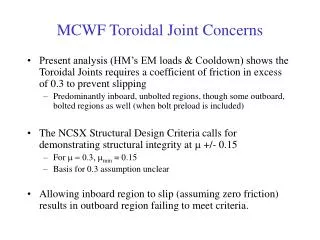
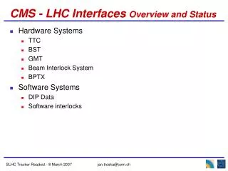
Mu needed on inner legs to prevent inner leg slip is too high C-C will be insulated and left to slide These IL’s will be welded to address high mu requirement. Mu based on data Mu with 2/3 criteria factor applied
With No Slip on inner legs, friction required on the outer legs to prevent them slipping is well within the friction capabilities of the alumina coated shims with excellent factors of safety. Highest m is ~0.16 vs. measured value of >0.6
Friction = 0.04 on Inner-leg region, mu = 0.4 everywhere else Bolt 1 Bolt 32 Inches No Inboard Bolt Friction Frictionless In board leg Peak Shear is 4.8 Kips Sliding is 19 mils
ab2tl ab2tru aatl bc2tru bc2tl aatr cc2t ab2trl ab2int aaint cc2int bc2int bc2trl bc2bru ab2inb aainb cc2inb bc2inb ab2br aabr cc2b bc2brl aabl bc2bl ab2bl -60 deg 0 deg bctl abtl bctru cct abtr bcint bctrl ccint abint bcinb bctrl ccinb abinb abbru ccb bcbl abbrl bcbrl abbl +60 deg Definition of shim segments
Our plan: weld the inner legs of all but C-C • Configuration: weld all intra-period interfaces and maintain a bolted / insulated interface between the field periods. • This addresses the inter-period friction & deflection requirements and bolt stress very nicely. • This is also very compatible with machine assembly procedures. A-A
C-C Slide Concept • Slide plates located top & bottom and along mid-section. • Plate thicknesses determined by metrology measurements. • Slide plates will be restrained to react friction loads with adequate F.S. • 3 additional bolts & friction shims will be added top and bottom to address bolt loading issue.