Download
1 / 32
480 likes | 1.07k Views
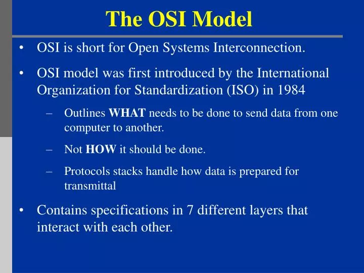
The OSI Model. OSI is short for Open System s Interconnection. OSI model was first introduced by the International Organization for Standardization (ISO) in 1984 Outlines WHAT needs to be done to send data from one computer to another. Not HOW it should be done.

E N D
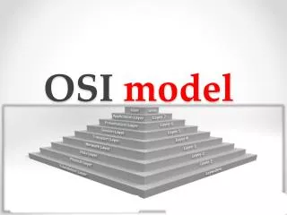
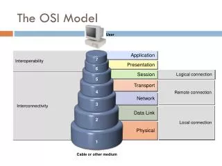
The OSI Model OSI is short for Open Systems Interconnection. OSI model was first introduced by the International Organization for Standardization (ISO) in 1984 Outlines WHAT needs to be done to send data from one computer to another. Not HOW it should be done. Protocols stacks handle how data is prepared for transmittal Contains specifications in 7 different layers that interact with each other.
What is “THE MODEL?” • Commonly referred to as the OSI reference model. • The OSI model is a theoretical blueprint that helps us understand how data gets from one user’s computer to another. • It is also a model that helps develop standards so that all of our hardware and software talks nicely to each other. • BOTTOM LINE: The OSI model aids standardization of networking technologies by providing an organized structure for hardware and software developers to follow, to insure there products are compatible with current and future technologies.
7 Layer OSI Model • Why use a reference model? • Serves as an outline of rules for how protocols can be used to allow communication between computers. • Each layer has its own function and provides support to other layers. • Other reference models are in use. • Most well known is the TCP/IP reference model. • We will compare the OSI and TCP/IP models in this presentation. • As computing requirements increased, the network modeling had to evolve to meet ever increasing demands of larger networks and multiple venders. • Problems and technology advances also added to the demands for changes in network modeling.
Evolution of the 7-Layers • Single Layer Model - First Communication Between Computer Devices • Dedicated copper wire or radio link • Hardware & software inextricably intertwined • Single specification for all aspects of communication Hardware & Software Hardware & Software 1 DEVICE B DEVICE A • http://www.howtheosimodelworks.com/
Evolution of the 7-Layers (2) Application Application Technical Standards Technical Standards • Two Layer Model • Problem: Applications were being developed to run over ever-increasing number of media/signaling systems. • Solution: Separate application aspects from technical (signaling and routing) aspects • Application Layer: Concerned with user interface, file access and file transfer 1 • http://www.howtheosimodelworks.com/
Evolution of the 7-Layers (3) Application Application Network Network Data-Link Data-Link Physical Physical • Four Layer Model - Network connectivity inherently requires travel over intermediate devices (nodes) • Technical Standards Level divided into Network, Data-link and Physical Layers 1 • http://www.howtheosimodelworks.com/
Evolution of the 7-Layers (3) cont. • Physical Layer • Describes physical aspects of network: cards, wires, etc • Specifies interconnect topologies and devices • Network Layer • Defines a standard method for operating between nodes • Address scheme is defined (IP) • Accounts for varying topologies • Data-Link • Works with Network Layer to translate logical addresses (IP) into hardware addresses (MAC)for transmission • Defines a single link protocol for transfer between two nodes
Evolution of the 7-Layers (4) Application Application Transport Transport Network Network Data-Link Data-Link Physical Physical • Five Layer Model – Increase Quality of Service (QOS) • Variable levels of data integrity in network • Additional data exchanges to ensure connectivity over worst conditions • Became the Transport Layer 1 • http://www.howtheosimodelworks.com/
Evolution of the 7-Layers (5) Application Application Session Session Transport Transport Network Network Data-Link Data-Link Physical Physical • Six Layer Model - Dialogue Control and Dialogue Separation • Means of synchronizing transfer of data packets • Allows for checkpointing to see if data arrives (at nodes and end stations) • Became Session Layer 1 • http://www.howtheosimodelworks.com/
Evolution of the 7-Layers (6) Application Application Presentation Presentation Session Session Transport Transport Network Network Data-Link Data-Link Physical Physical • The Seven Layer OSI Model - Addition of Management and Security • Standardizing notation or syntax for application messages (abstract syntax) • Set of encoding rules (transfer syntax) • Became the Presentation Layer 1 • http://www.howtheosimodelworks.com/
7 Layer OSI Model • Benefits to using the OSI reference model. • Breaks down communication into smaller, simpler parts. • Easier to teach communication process. • Speeds development, changes in one layer does not effect how the other levels works. • Standardization across manufactures. • Allows different hardware and software to work together. • Reduces complexity.
What Each Layer Does 2 2Cisco Academy Program Semester 1
Application Layer • Gives end-user applications access to network resources • Where is it on my computer? • Workstation or Server Service in MS Windows 3 3Graphic courtesy ofhttp://www.hawkclan.com/zxonly/iso/slide2.html
Presentation Layer • Provides common data formatting between communicating devices • Components make sure the receiving station can read the transferred data 3 3Graphic courtesy ofhttp://www.hawkclan.com/zxonly/iso/slide2.html
Session Layer • Allows applications to maintain an ongoing session • Example – NetBIOS • Where is it on my computer? • Workstation and Server Service (MS) • Windows Client for NetWare (NetWare) 3 3Graphic courtesy ofhttp://www.hawkclan.com/zxonly/iso/slide2.html
Transport Layer • Provides reliable data delivery • It’s the TCP in TCP/IP • Receives info from upper layers and segments it into packets • Can provide error detection and correction 3 3Graphic courtesy ofhttp://www.hawkclan.com/zxonly/iso/slide2.html
Network Layer • Provides network-wide addressing and a mechanism to move packets between networks (routing) • Responsibilities: • Network addressing • Routing • Examples: • IP from TCP/IP • IPX from IPX/SPX 3 3Graphic courtesy ofhttp://www.hawkclan.com/zxonly/iso/slide2.html
Network Addresses • Network-wide addresses • Used to transfer data across subnets • Used by routers for packet forwarding • Example: • IP Address • Where is it on my computer? • TCP/IP Software
Data Link Layer • Places data and retrieves it from the physical layer and provides error detection capabilities 3 3Graphic courtesy ofhttp://www.hawkclan.com/zxonly/iso/slide2.html
Sub-layers of the Data Link Layer • MAC (Media Access Control) • Gives data to the NIC • Controls access to the media through: • CSMA/CD Carrier Sense Multiple Access/Collision Detection • Token passing • LLC (Logical Link Layer) • Manages the data link interface (or Service Access Points (SAPs)) • Can detect some transmission errors using a Cyclic Redundancy Check (CRC). If the packet is bad the LLC will request the sender to resend that particular packet.
Physical Layer • Determines the specs for all physical components • Cabling • Interconnect methods (topology / devices) • Data encoding (bits to waves) • Electrical properties • Examples: • Ethernet (IEEE 802.3) • Token Ring (IEEE 802.5) • Wireless (IEEE 802.11b) 3 3Graphic courtesy ofhttp://www.hawkclan.com/zxonly/iso/slide2.html
Physical Layer (cont’d) • What are the Physical Layer components on my computer? • NIC • Network Interface Card • Has a unique 12 character Hexadecimal number permanently burned into it at the manufacturer. • The number is the MAC Address/Physical address of a computer • Cabling • Twister Pair • Fiber Optic • Coax Cable
Each layer contains a Protocol Data Unit (PDU) PDU’s are used for peer-to-peer contact between corresponding layers. Data is handled by the top three layers, then Segmented by the Transport layer. The Network layer places it into packets and the Data Link frames the packets for transmission. Physical layer coverts it to bits and sends it out over the media. The receiving computer reverses the process using the information contained in the PDU. How Does It All Work Together 2 2Cisco Academy Program Semester 1
A- Write a 20 page letter to a foreign country. P- Translate the letter so the receiver can read it. S- Insure the intended recipient can receive letter. T- Separate and number pages. Like registered mail, tracks delivery and requests another package if one is “lost” or “damaged” in the mail. N- Postal Center sorting letters by zip code to route them closer to destination. D- Local Post Office determining which vehicles to deliver letters. P- Physical Trucks, Planes, Rail, autos, etc which carry letter between stations. The Postal Analogy Application Presentation Session Transport Network Data-Link Physical How would the OSI compare to the regular Post Office
The TCP/IP Model • Another Model is the TCP/IP Model. • There is no universal agreement regarding how to describe TCP/IP with a layered model. • Most descriptions present three to five layers. • We use the four layer structure that incorporates the Presentation and Session layers with the Application layer.
Comparing TCP/IP With OSI 2 2Cisco Academy Program Semester 1
The TCP/IP Model (4 Layer) • Application Layer • Interacts with user processes • Transport Layer • TCP guarantees data is received and sent accurately • Internet Layer • IP separates upper layers from the network and manages the connections across the network • Network Access Layer • Incorporates the Network and Physical layers of the OSI model 4 4http://www.pku.edu.cn/academic/research/computer-center/tc/html/TC0102.html
TCP/IP and the OSI Model • TCP/IP is the most commonly used network communication protocol suite. It is the default protocol for the global internet. • - Set of protocols which function within the framework of the OSI Model • - Each protocol communicates with other protocols at next levels • - Other protocols can be mapped to the OSI model. This link shows a great breakout of many: • http://www.lex-con.com/osimodel.htm 5 5 http://www.lex-con.com/protocols/ip.htm
Protocols • For a great graphic of protocol stacks in relationship to the OSI model, visit http://www.lex-con.com/osimodel.htm • For more information on the OSI model, including an animated graphic and various protocol information, visit http://www.certyourself.com/OSIguide.shtml
7 - Application All 6 - Presentation People 5 - Session Seem 4 - Transport To 3 - Network Need 2 - Data Link Data 1 - Physical Processing Remembering the 7 Layers 1 - Physical Please 2 - Data Link Do 3 - Network Not 4 - Transport Throw 5 - Session Sausage 6 - Presentation Pizza 7 - Application Away
How the OSI and TCP/IP Models Relate in a Networking Environment
Bibliography • http://www.howtheosimodelworks.com , Charles C. Botsford, 2001. • https://cisconetacad.net, Cisco Academy Connection Editors, 2002. • http://www.hawkclan.com/zxonly/iso/slide2.html • http://www.pku.edu.cn/academic/research/computer-center/tc/html/TC0102.html, William L. Whipple & Sharla Riead, 1997. • http://www.lex-con.com/protocols/ip.htm, Lexicon Computing, Dallas TX, 2002