Download
1 / 56
560 likes | 669 Views
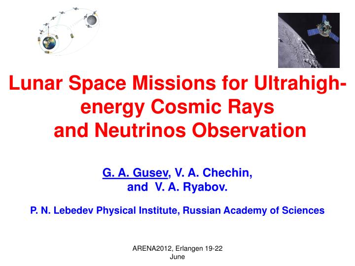
Lunar Space Missions for Ultrahigh-energy Cosmic Rays and Neutrinos Observation G. A. Gusev , V. A. Chechin, and V. A. Ryabov. P. N. Lebedev Physical Institute, Russian Academy of Sciences.

E N D
Lunar Space Missions for Ultrahigh-energy Cosmic Rays and Neutrinos Observation G. A. Gusev, V. A. Chechin, and V. A. Ryabov. P. N. Lebedev Physical Institute, Russian Academy of Sciences ARENA2012, Erlangen 19-22 June
Two stages of a lunar experiment with the regolith as a target for the interaction of ultrahigh-energy cosmic rays and neutrinos are considered. The first stage deals with the LORD experiment within the framework of the Luna-Glob space mission scheduled for 2016. The current status of the LORD-instrumentation development is discussed. The aperture of the lunar orbital radio detector exceeds all existing ground-based arrays. Successful realization of the LORD experiment will make it possible to start the second stage of the program. Multi-satellite lunar orbital systems are proposed to increase the aperture and the measurement informativity and accuracy. ARENA2012, Erlangen 19-22 June
Outlook of Presentation • Problems of ultrahigh-energy cosmic rays and neutrinosobservation. • LORD spaceexperiment and design of apparatus • Multi-satellite circumlunar array, the results of Monte Carlo simulation • Conclusion ARENA2012, Erlangen 19-22 June
The Main Goal of the LORD Experiment The primary goal of the LORD experiment is the detection of ultrahigh-energy cosmic rays and neutrinos. An investigation of the nature and spectra of cosmic particles with energies E ≥ 1020 eV (“ultra-high energies”, UHE) is one of the most challengingproblems of modern physics and astrophysics. Information on these particles is important for solving fundamental problems of astrophysics and particle physics relating to cosmic ray sources and acceleration mechanisms. ARENA2012, Erlangen 19-22 June
Currently we have a very controversial and paradoxical situation in UHE region. We know neither the nature of UHE particles, nor their sources or processes where they were accelerated to such extremely high energies. The many facts of the experimental observations at different CR detectors contradicts to the current understanding of the Universe, because a flux of these energetic particles must be suppressed, owing to the GZK CR spectrum cutoff (EGZK ≈ 7∙1019 eV, Pierre Auger Observatory (PAO) spectrum extrapolation dN/dE ~ E-4.3 ) caused by the interaction with microwave cosmic background. For resolving these contradictions, new independent measurements are necessary. ARENA2012, Erlangen 19-22 June
Currently radiomethod is used as the basis for a number of experiments and projects on the ultrahigh-energy particle detection in such radio-transparent media as the atmosphere, salt domes and ice sheets of Antarctic and Greenland. LORD EXPERIMENT ARENA2012, Erlangen 19-22 June
Cosmic rays, neutrino interact with regolith and produce coherent Cherenkov radiation pulse, which after refraction on the Moon surface goes out to vacuum. It can be observed by the LORD apparatus, amplitude, polarization, frequency spectrum being measured. Its aperture is more than one order comparatively PAO one. ARENA2012, Erlangen 19-22 June
Limits for CR and Neutrino Fluxes and LORD Performance ARENA2012, Erlangen 19-22 June
LORD apertures for UHECR & UHEN detection are higher than in all ongoing experiments (with one exception for neutrino detection by LOFAR in the energy range more, than 1022 eV) and for energy 1021 eV are about3·105 km2 sr for UHECRand 4·103 km2 sr for UHEN (AUGER aperture for UHENabout 100 km^2 sr) ARENA2012, Erlangen 19-22 June
Lay-out of Luna-Glob Apparatus ARENA2012, Erlangen 19-22 June
Flight Module of Luna-Glob ARENA2012, Erlangen 19-22 June
Block Diagram of LORD Detector Flight Payload Controller RF-1 Scientific instruments Data Acquisition System 2 Gsps, 10 bit, 2 x 4096 samples Calibration RF-2 Antenna System Spacecraft 27 V Power Supply 16 Mbyte memory Commands Data ARENA2012, Erlangen 19-22 June
LORD DEVICE 306 Registration system Antenna 1 328 500 480 1514 306 dimensions are in millimeters Antenna 2 500 1514 ARENA2012, Erlangen 19-22 June
Antenna system of LORD device Frequency band – 200-800 MHz Gain ~ 7.5 dB Polarization - LP & RP Length =1515 mm Diameter= 500 mm ARENA2012, Erlangen 19-22 June
Antenna with low noise preamplifier (LNA) • LNA 40 dB, NF=1.1dB, TN = 30K ARENA2012, Erlangen 19-22 June
Registration block of the LORD equipment L×W×H = 420 mm ×320 mm×80 mm, Weight= 12 kg, Power Supply = 27 V, 60 W ARENA2012, Erlangen 19-22 June
Low noise amplifier for the LORD equipment ARENA2012, Erlangen 19-22 June
E-cards for the LORD equipment ARENA2012, Erlangen 19-22 June
Currently, all electronic components are investigated with a view to develop performance in order to improve the accuracy of determining the physical parameters in the experiment LORD ARENA2012, Erlangen 19-22 June
Main characteristics of broadband (200-800 MHz) antennas • Voltage Standing Wave Ratio of Antenna (VSWR) • - Directivity diagrams at different frequencies • Cross polarization directivity diagrams at different frequencies • - 3-D directivity diagramsat different frequencies ARENA2012, Erlangen 19-22 June
Voltage Standing Wave Ratio of Antenna (VSWR) VSWR = (1+γ)/ (1-γ) , where γ is reflection coefficient. In our antenna 0.09≥ γin the frequency band 200-800 MHz • 300 400 500 600 700 800 900 1000 • Frequency (MHz) ARENA2012, Erlangen 19-22 June
Directivity diagram for 200 MHz (Right polarisation) Main lobe magnitude = 8,4 dB Angular width (3dB) = 68,8 deg. Side lobe level = -10,2 dB -200 -150 -100 -50 0 50 100 150 200 Theta (Degree) ARENA2012, Erlangen 19-22 June
3-D directivity diagram 200MHz ARENA2012, Erlangen 19-22 June
Cross polarization directivity diagram 200 MHz Main lobe magnitude = -4.7 dB Angular width(3 dB) = 74.6 deg Side lobe level = -6.3 dB -200 -150 -100 -50 0 50 100 150 200 Theta (Degree) ARENA2012, Erlangen 19-22 June
Directivity diagram 300 MHz(Right polarisation) Main lobe magnitude = 9,2 dB Angular width (3dB) = 71,8 deg. Side lobe level = -35,9 dB -200 -150 -100 -50 0 50 100 150 200 Theta (Degree) ARENA2012, Erlangen 19-22 June
3-D directivity diagram 300MHz ARENA2012, Erlangen 19-22 June
Cross polarization directivity diagram 300 MHz Main lobe magnitude =-13,1 dB; angular width(3 dB) =42,5deg; side lobe level=-11,7 dB -200 -150 -100 -50 0 50 100 150 200 Theta (Degree) ARENA2012, Erlangen 19-22 June
Directivity diagram 500 MHz (Right polarisation) Main lobe magnitude =9,2 dB; angular width(3 dB) =70,9 deg; side lobe level=-38,9 dB -200 -150 -100 -50 0 50 100 150 200 Theta (Degree) ARENA2012, Erlangen 19-22 June
3-D directivity diagram 500MHz ARENA2012, Erlangen 19-22 June
Cross polarization directivity diagram 500 MHz Main lobe magnitude =-13,5 dB; angular width(3 dB) =43,7deg; side lobe level=-7,4 dB -200 -150 -100 -50 0 50 100 150 200 Theta (Degree) ARENA2012, Erlangen 19-22 June
Directivity diagram 800 MHz Main lobe magnitude =6 dB; angular width(3 dB) =112 deg; side lobe level=-20,1 dB ARENA2012, Erlangen 19-22 June
3-D directivity diagram 800MHz (Right polarisation) ARENA2012, Erlangen 19-22 June
Cross polarization directivity diagram 800 MHz Main lobe magnitude =-2,7 dB; angular width(3 dB) = 57deg; side lobe level = -7,7 dB -200 -150 -100 -50 0 50 100 150 200 Theta (Degree) ARENA2012, Erlangen 19-22 June
Some simulation results for an arrayof circumlunar radio detectors as the LORD ARENA2012, Erlangen 19-22 June
Sketch of four satellite circumlunar array, using LORD detectors 1 2 3 4 ARENA2012, Erlangen 19-22 June
Principles of construction of the lunar satellite system for radio detection of ultrahigh-energy particles - Minimum number of detectors - 3 - spatial separation - latitude, longitude, altitude - recording time synchronization of signals in different detectorsallowsto localize the source - maximum distance of separation - 400 km - minimum distance of separation - 100 km ARENA2012, Erlangen 19-22 June
Why do we need many satellite system radio detection in the context of the LORDexperiment? First, the spatial separation of detectors, even at small distances provided synchronization allows us to localize the source of radio emission. This makes it possible to solve the inverse problem of recovering the cascade energy, a large number of measured data being significant. For example, in the case of the four detectors, each event is recorded in 8 channels, so that there are 8 amplitudes and 8 signal spectra in a wide band. In the favorable case,when the scattering is not significant, it becomes also possible to determine the polarization of the electric field in each detector. This allows to discriminate more efficientlythe cascade signal from the accidental signals. Second, there is the trivial possibility of using several widely separated and hence independent satellites to increase the aperture of the event logging. ARENA2012, Erlangen 19-22 June
When it comes to choosing the main parameters of the array of lunar satellites, the main they are the height and spacing between them. As for the spacing in height, it is always due to the inaccuracy of the satellite into orbit. These discrepancies enough to a spacing in height, sufficient to determine the elevation angle of the beam recorded as antenna spacing in height by several meters provides sufficient accuracy of the elevation. ARENA2012, Erlangen 19-22 June
δθ δθ δφ Fig. Satellite spacing in latitude and longitude must be such that the «radiation spot" at an altitude satellites was comparable with the distances between satellites, as in this case, all measured at various satellite parameters: amplitude, polarization, angles of escape of radiation from the surface of the moon, time of arrival signals - will be significantly different, allowing us to increase the chances of solving the inverse problem of determining the energy cascade. For this purpose, we used simulation the registration of Cerenkov radiation from the cascade in an array of four satellites spaced as follows: three satellites are spaced in latitude (at the angle δθ) and one in longitude (at the angle δφ) at the same angular distances (see. Fig.) ARENA2012, Erlangen 19-22 June
Parameters of radio detector array, used in simulations Frequency band 200 – 400 MHz Satellite altitudes 200 – 2000 km Latitude and longitude separation 2 – 15 degrees electric fieldthresholds 0.1 – 0.2 μV/m MHz Exposure time 1 year ARENA2012, Erlangen 19-22 June
AUGER CR spectrum, used in simulations ARENA2012, Erlangen 19-22 June
CR registration. Altitude –1000km. Separation – 2 degrees. Threshold – 0.1mkV One satellite – 233 Two satellites – 196 Three satellites – 172 Four satellites – 168 ARENA2012, Erlangen 19-22 June
CR registration. Altitude –1000km. Separation – 12 degrees. Threshold – 0.2mkV One satellite – 223 Two satellites – 73 Three satellites – 12 Four satellites – 8 ARENA2012, Erlangen 19-22 June
CR registration. Altitude –1000km. Separation – 2 degrees. Threshold – 0.2mkV One satellite – 28 Two satellites – 24 Three satellites – 20 Four satellites – 19 ARENA2012, Erlangen 19-22 June
CR registration. Altitude –1000km. Separation – 12 degrees. Threshold – 0.2mkV One satellite – 23 Two satellites – 3 Three satellites – 0 Four satellites – 0 ARENA2012, Erlangen 19-22 June
We can see that for 4 satellites cosmic ray array (CRA) a large separation of satellites results in fast decreasing array aperture. It means that for separations more than 12 degrees CRA transforms in 4 autonomous LORD detectors, therefore the total aperture of the system of four independent detectors is increased 4-fold. Technical implementation presents no difficulties. ARENA2012, Erlangen 19-22 June
Neutrino spectrum from decay of massive particle with mass 1025 ev ARENA2012, Erlangen 19-22 June
Results of joint neutrino event registration by four satellites, having the latitude and longitude differenceof 10 degrees One satellite – 40 Two satellites – 34 Three satellites – 27 Four satellites – 22 NNS/NCR = 22/8 ≈ 3 ARENA2012, Erlangen 19-22 June
Interestingly, in the case of registration of neutrinos from the decay of superheavy particles with masses 1025 eV, a significant separation of satellites at 12 degrees of latitude does not lead to a marked decrease in statistics (losses 45%, for CR – 97%) as comparing with one detector. This means that an array (NA) of radio detectors at a large spatial separation of detectors about 15 degrees of latitude is mainly to detect neutrinos. ARENA2012, Erlangen 19-22 June
Further simulations aiming the detection of neutrino Separation 13 degrees, altitude 1200 km NNS/NCR = 19/4 ≈ 4.8 Separation 13 degrees, altitude 1500 km NNS/NCR = 5/1=5 Separation 13 degrees, altitude 1700 km NNS/NCR = 15/2.5 ≈ 6 Separation 13 degrees, altitude 1800 km NNS/NCR = 15/2 ≈ 7.5 ARENA2012, Erlangen 19-22 June