Download
1 / 17
170 likes | 305 Views
Source Controller software status. HCAL fall meeting Oct 13-15, 2005 Ianos Schmidt The University of Iowa. System. HE+. HO0. HE-. HO+1,+2. HO –1,-2. HB+. HB-. HF+. HF-. Services: Air drivers Electric drivers. Total 10 16. 2 3. 2 3. 0 2. 3 3. 0 0*. 0 0*. 0 0*.

E N D
Source Controller softwarestatus HCAL fall meeting Oct 13-15, 2005 Ianos Schmidt The University of Iowa
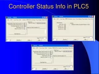
System HE+ HO0 HE- HO+1,+2 HO –1,-2 HB+ HB- HF+ HF- Services: Air drivers Electric drivers Total 10 16 2 3 2 3 0 2 3 3 0 0* 0 0* 0 0* 3 3 0 2 Zone safety interlocks Air supply pressure switches New Crate of controller boards Crate of controller boards DIM Client(s) Power supplies 5V,18V,24V Local control laptop DIM Server RS-485 links RS-232 directly to individual boards. * HO will use a temporary portable system
Software component diagram Tools for testing, configuration and programming of controllers.+ Controller source code. Laptop Run Control Control PC RS-232 DIM Server RS-485 DIM clients DIM clients DIM client Database ? Controller boards Local disk Local tools for configuration, testing, and compiling code • Config. info • Tube maps • Source code Config. info Tube maps Source code Controller code and settings in flash memory
Air driver controller code • Development of the air driver specific functions has started. • Working representations of all functions exist and operate correctly with the DIM server, but need refinement of fault detection and handling. • Experience with the electric drivers has shown that robust fault detection is necessary to protect the equipment from damage. • Next step is merge the air driver specific functions with the core structure of the most recent version for the electric drivers. • Expect to have Version1 of code ready by end of October.
Electric driver controller code • The most recent version of the code is presently in use at SX5 for HE- sourcing. • Code is very mature, but needs more robust fault detection in init sequence. • Speed control is the only remaining electric driver specific feature that may still be implemented. • Speed control code has already been written and appears to work, (ie. control loop is stable), but introduces much more complexity which has yet to be fully evaluated. -This is not a critical item at the moment.
Remaining controller code workcommon to both driver types • Restructuring of status information and fault handling • Restructuring will likely be necessary after completion of the air driver specific functions to provide a consistent hardware independent interface to the DIM server. • Reel init button so wire can be retracted when DCS is not functional • CRC checking of controller code. • Started investigating ways of getting a CRC code into the programmed device. No easy way to do it. Presently there are three possible solutions: 1. Custom “plug in” that interfaces with the programming software. 2. Custom tool that inserts it into the hex file used to program the device. 3. Implement a way to program the CRC code using the controller code itself, similar to the way configuration parameters are programmed.
Remaining controller code work cont. • Geiger counters • Geiger counter code has not been started but should not be too difficult to implement, but It is not apparent that we need this functionality. • Geiger counters (provided by Purdue) use transformers. Proper operation is not likely in a strong magnetic field excluding their use in the PSD’s. • Geiger counter use for TSD’s may be useful but should only be considered as a hardware checking tool, not as a part of the required safety equipment that falls under the responsibility of TIS/Radioprotection. • Geiger counter signals require some interpretation. • Testing and more testing… • there are many possible fault conditions which tend to conspire. It is certain that there are remaining “undesirable features” to be discovered. -Need Feedback from use in the field.
DIM Server SDriver objects. One/controller RSport objects. One per serial port. SDriver object 1 DIM SDriver object 2 RSport objects SDriver object 3 SDriver object 4 SDriver object n HWconfig object DIM info and command service objects configuration file
DIM Server code status The DIM server code has been completely rewritten. The new version (incomplete) is presently in use at SX5 for both HB+ and HE- sourcing. • New features: • Allows multiple controllers to share serial ports (RS485 buss) • DIM server is aware of driver fault conditions • “fatal error” bit implemented to inform runcontrol of a fault condition (Causes runcontrol to abort sequence). • Hardware configuration file implemented to specify driver specific information as well as global parameters.
Remaining DIM server work • Implementation of Partition locking • implementation of map files • Implementation of the following DIM services: • Driver name (text string). • Map file name (text string). • Name of current index (text string). • Messages from server (text string). • Load map file command service (text string). • Definition of interface with runcontrol
Run control interface The interface to run control needs to be defined. There are two outstanding issues: * Two competing ideas as to how to organize the control structure have been proposed. 1. Have the majority of operator interaction be through run control. • Requires handshaking with the DIM server to share info. 2. Have most of the interaction through a PVSS DIM client. • Requires no additional changes to runcontrol. *Run control presently can only communicate with one driver. • How are drivers to be specified? At the moment driver specific DIM services are specified by the driver number. This number is the address number derived from the controller crate backplane (slot No.) This is not very intuitive and likely to cause mistakes (namely operating the wrong driver!). • A possible solution is to use driver name, not address.
Other info.:Controller software overview Each controller board contains a Philips 89C51RB2 microcontroller. The code for these is written in the native “8051 compatible” assembly language. The Assembly code is complied using ASM51, and the controllers are programmed using either WINISP or Flash Magic programming tools. All of these tools are free, and operate under Windows. The programming interface is non-proprietary and fully documented allowing the option to implement a custom programmer on any platform in the future if necessary. This code provides all functionality to operate the Purdue wire source drivers, and to provide a standard interface, regardless of driver type, via RS-232 or RS-485 to the DIM server. Information that describes the specific hardware and related behaviors is stored in a block of flash memory which is transferred to RAM at boot up. These values can be modified and resaved, or default values can be restored via the serial interface. Generally speaking these parameters will only need to be changed if the driver hardware or control electronics are changed.
Other info.:DIM Service information COMMAND SERVICES • Command name Format Parameter1 Parameter2 1. "CMS/HCAL/RSRC[_ServerSubname]/{DEV}/INIT I:2 Index Reel 2. "CMS/HCAL/RSRC[_ServerSubname]/{DEV}/GO" I:2 Index Reel 3. "CMS/HCAL/RSRC[_ServerSubname]/{DEV}/SCAN" I:2 Index_from Index_to 4. "CMS/HCAL/RSRC[_ServerSubname]/{DEV}/STOP" 5. "CMS/HCAL/RSRC[_ServerSubname]/DEBUG" I:2 Device(0 means all) level(0-3) Information services. -------------------- 1. "CMS/HCAL/RSRC[_ServerSubname]/STATUS" I:16 Contains status words (see lower) for all the 16 drivers 2. "CMS/HCAL/RSRC[_ServerSubname]/{DEV}/STATUS" I Service sends the structure SrcInfo: typedef struct { int message_counter; timeval time_stamp_1; //{int seconds; int mkseconds;} int status; int index_counter; int reel_counter; int motor_current; int speed; // not implemented yet in the driver timeval time_stamp_2; (int 0; int 0;} will be filled in the Event Builder }SrcInfo; * Does not include services for configuration information and tube maps.
Other info.:Server log file The DIM server writes a local log file for each driver which contains an entry for each change in status. For changes in controller status an entry consists of all controller state information. Sample from log file: 10:03:00 254 160 0000 0010 884 2 0 107 0000 0000 0000 0000 0000 0000 10:03:04 254 160 0000 0011 583 2 48 107 0000 0000 0000 0000 0000 0000 10:03:05 254 160 0000 0010 634 2 56 107 0000 0000 0000 0000 0000 0000 10:03:15 254 160 0000 0000 5 2 0 24 0000 0000 0000 0000 0000 0000 10:04:44 Command SCAN recived with parameters: 7 7 10:04:44 254 160 0000 0110 6 2 5 78 0000 0000 0000 0000 0000 0000 10:04:45 254 160 0000 0000 0 2 0 78 0000 0000 0000 0000 0000 0000 10:04:45 254 160 0000 0010 0 2 0 105 0000 0000 0000 0000 0000 0000 10:04:46 254 160 0000 0000 0 2 0 107 0000 0000 0000 0000 0000 0000 10:04:46 254 160 0000 0101 0 2 37 80 0000 0000 0000 0000 0000 0000 10:04:47 254 160 0000 0000 0 3 0 78 0000 0000 0000 0000 0000 0000 10:04:47 254 160 0000 0101 0 3 47 78 0000 0000 0000 0000 0000 0000 10:04:49 254 160 0000 0000 0 4 0 78 0000 0000 0000 0000 0000 0000 10:04:49 254 160 0000 0101 0 4 53 78 0000 0000 0000 0000 0000 0000 10:04:50 254 160 0000 0000 0 5 0 78 0000 0000 0000 0000 0000 0000 Mon Jul 19 add comm status reel ind I V Errors0 Errors1 Warnings 10:04:50 254 160 0000 0101 0 5 36 78 0000 0000 0000 0000 0000 0000 10:04:51 254 160 0000 0000 0 6 0 78 0000 0000 0000 0000 0000 0000 10:04:52 254 160 0000 0101 0 6 42 78 0000 0000 0000 0000 0000 0000 10:04:53 254 160 0000 0000 0 7 1 78 0000 0000 0000 0000 0000 0000 10:05:03 254 160 0000 0001 3 7 44 105 0000 0000 0000 0000 0000 0000 10:06:18 254 160 0100 0001 6534 7 0 107 0000 0000 0000 0000 0000 0100
Other info.:Tube maps Tube maps from files or a database will be used to provide specific information about the tubes that are connected to the drivers. Which map to use can be specified from a DIM client, otherwise the default specified in the configuration data will be used. Each entry is associated with the index number from the related driver. A tube map contains the following information: Global: • Map title • Driver type • First and last tube number • Optional default settings for the driver (parameter overrides) Tube specific: • Tube number. • Tube name (ie. “HE+1, sector 2, slice 1, layer 5”) • Partition number • Tube status (skip, ok, warn, test) • Maximum length • Start of detector/area of interest • (Optional settings such as motor voltage/speed for extend/retract, in/out of detector)
Other info:DIM clients A Visual source controller client is under development using Borland tools. This provides an easy to use graphical interface that allows use all the available DIM services and commands. Ultimately this will be implemented in PVSS. Run control contains a client for merging the source controller data with DAQ data. Run control also provides sequence files to automate the sending of DIM commands. The run control DIM interface will have to be updated to use tube map and configuration information.
Other info.:Miscellaneous Other software • Controller test program for sending raw serial commands to a controller card. This is to be used while the laptop is directly connected to the RS-232 connector on the front of a controller card. When connected in this way the controller is automatically dropped from the RS-485 buss allowing maintenance and testing of individual cards while the other cards are in operation, or for testing cards individually outside of the crate. • Tool for setting controller parameters and saving them to flash memory. Although this will rarely need to be done it is tedious to do using the raw serial commands. • DID (Dim display) Tool part of the DIM package for testing DIM servers. • Borland BCB for building code.