Download
1 / 22
220 likes | 322 Views
W trigger upgrade simulation. Kazuya Aoki Kyoto Univ. Muon Physics and Forward Upgrades Workshop Santa Fe, June 2004. MENU. MuTrLL1 idea simulation results (Kazuya’s) influence on current system (Kohei’s) MuPCLL1 idea simulation results ( Wei’s ). MuTr LL1 - basic idea.

E N D
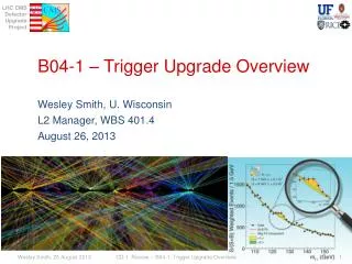
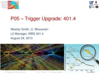
W trigger upgrade simulation Kazuya Aoki Kyoto Univ. Muon Physics and Forward Upgrades Workshop Santa Fe, June 2004
MENU • MuTrLL1 idea • simulation results (Kazuya’s) • influence on current system (Kohei’s) • MuPCLL1 idea • simulation results ( Wei’s )
MuTr LL1 - basic idea • Accept high momentum tracks. • Measure sagitta using hits at station 1,2 and 3 • Read out 1 / 1 / 1 planes for LL1 • We have 6 / 6 / 4 planes in MuTr • Read out non-stereo type planes Non-stereo sagitta: the difference between The actual hit at station#2 and interpolated position
MuTr LL1 - electronics ~10usec AMU ADC data For offline analysis MuTr Cathode CPA (Cathode PreAmp) BBCLL1 GL1 MuIDLL1 Hit pattern Amp Discri FPGA (MuTrLL1) ~80nsec MuTr LL1 electronics
MuTr LL1 - algorithm m+ m- Strips at Station 1 Strips at Station 3 Strips at Station 2 INPUT: single m 15GeV/c vertex z=0 accept Dstrip<=1 ~25 Dstrip :Sagitta at station 2
Estimate RF and Eff~Simulation procedure • Rejection Factor • Efficiency PYTHIA Signal(W events) Background PISA Response chain Hit information of strips Trigger simulator
Simulation procedure~ event generator Inclusive charged hadron pT spectra • Software and PDF • PYTHIA Ver6 • CTEQ5M1 • Settings for background • <kT>=2.5GeV/c , kT<10GeV/c • MSEL=2(MinBias : total s) • No cuts applied • 1M events • Agrees well with UA1 data • Settings for signal • MSEL=12 • Cuts applied • W should decay into m • The m should have PT>20GeV/c and -1.2>h>-2.2 or 1.2<h<2.4 • 50k events pp sqrt s = 200GeV pp sqrt s = 500GeV
Simulation procedurePISA • Vertex distribution • rms of z = 17 Fitted func. (gaus) BBC Z vertex RUN92446(REAL DATA)
Definitions • Rejection Factor • Efficiency MinBias(Total s) # of triggered events (MuTrLL1 X MuIDLL1) # of triggered events (MuTrLL1 x MuIDLl1) W decays into m which satisfy the following: pT>20GeV/c and -1.2>h>-2.2 or 1.2<h<2.4
Rejection & Efficiency Using only 2 stations Using 3 stations ( MuTr LL1 x MuID LL1) Enough rejection factor. Good efficiency 3 Eff = [MuIDLL1] x [MuTr acc] x [MuTr trigger plane eff.] = 66% 95% 79% 96% Dstrip :Sagitta at station 2
Requirement for preamp • Drift time ~80 nsec within bunch interval • Integration time of preamp should be less than 100nsec. • We are testing Amp shaper discri chip ( made by Tanimori et. al.) with chamber • 80 nsec shaping time.
Observed by oscilloscope Without preamp Cosmic ray MuTrtest chamber • Test chamber • Contribution from D. Fields • One layer of station 1 • Electronics R&D • Preamp • Trigger logic. MuTr test chamber at Kyoto. 140cm
What happens when we just replace current electronics…. AMU ADC data For offline analysis MuTr Cathode CPA BBCLL1 GL1 MuIDLL1 ASD FPGA (MuTrLL1) (Amp Shaper Discri.) MuTr LL1 electronics
J/y mass resolution Requirement for track 432/664 432/553 322/553 Eff. 86% Res. degrade Eff. Recovered Res. unchanged plots by Kohei
PC2 Pad Chamber in PISA PC1 Not used IP St.#1 St.#2 MuPC hits distribution St.#3 MuID PC1/PC2/MuID symset matching Df cut. Two Pad Chamber, i.e. pc1/pc2 has been inserted into forward region. All are sandwich of 2 layers of 0.02cm s2 glass and 1,0cm G10 gas. PC1 is a 16 edge polygon with R=110/170cm when in front of /behind station #1. PC2 is a square with edge length 1000cm. Simulation by Wei Xie
Tracking trigger: LUT between PC1/PC2/Symset Then we do look-up among pc1/pc2/symset. Single muons with mom=4-10GeV/c is passed through PISA. Only multiple-scattering and energy loss are turned on. Here shows only tile size: PC1/10cm, PC2/30cm and PC1 in front of station #1 (1). PC1 is in front of station #1. Tile size PC1(10cm), PC2(30cm). Perfect resolution Full PISA simulation including trigger processors enough rejection factor is achieved. Simulation by Wei Xie
summary • MuTr LL1 x MuID LL1 will have enough RF. • R&D of Electronics in Kyoto. • Pad chamber + MuID symset info will have enough RF. • Hardware feasibility study is work in progress.
choose hit strip charge 二値化 Discri. • Charge is induced 2 or 3 consecutive strips. • Discriminate the signals • Choose the center strip as the hit • The difference between peak strip and center strip is <=1 • This is gives enough resolution Thresh. Choose the center strip As the hit REAL DATA counts The difference
MuTr LL1 - electronics ~10usec MuTr Cathode CPA Offline analysis ~80nsec trigger ASD Digital out trigger MuTr Cathode ASD shaper Offline analysis Analog out
Cosmic ray MuTr LL1 MuTr signal MuTr test chamber at Kyoto. Amp-shaper-discri Hit pattern Programmable Circuit (FPGA) MuTr LL1 140cm
1.Making lookup table m+ m- • For each strip at St#1 • get hit strip dist. at St#3 • Fit with gaus func. • get lower and upper limit • (+/- 3s from mean) • To reduce the data size • Collect all lower and upper limits and fit with straight line INPUT: single m 15GeV/c vertex z=0 For each strip at St#1 Upper limit lower limit Upper limit Fit with straight line Lower limit