Download
1 / 32
1.37k likes | 3.19k Views
Chapter 3: HYDRAULICS AND PNEUMATICS. Engineering Mathematics. Introduction/Description. Individually, and in teams, you will build and evaluate a Stirling engine, calculate hydraulic force multiple factor, build linear, rotational, and lifting hydraulic systems,

E N D
Chapter 3: HYDRAULICS AND PNEUMATICS Engineering Mathematics
Introduction/Description Individually, and in teams, you will • build and evaluate a Stirling engine, • calculate hydraulic force multiple factor, • build linear, rotational, and lifting hydraulic systems, • build, design, and test a hydraulic arm that meets design criteria and accomplishes a given task, and • create a presentation about your hydraulic system, documentation the mathematics used and tested.
Chapter 3: Outline Introduction to Fluid Power Pressure and Pascal’s Principle Bernoulli’s Principle
Objectives and Results • Explain the Stirling engine heat cycle. • Explain and apply Pascal's Law. • Explain how linear, rotation, and lifting hydraulic systems are formed. • Explain and demonstrate how discrete hydraulic systems can be combined to form a more complex and functional system. • Calculate thermal efficiency of a Stirling engine.
Objectives, cont. • Calculate a system’s hydraulic force multiplication factor. • Graph and interpret data from experiments and tests, • Build a Stirling engine. • Build linear, rotational, and lifting hydraulic systems. • Practice the design process by designing and building a hydraulic arm that meets design criteria and accomplishes a given task.
Results • Complete the various worksheets and projects. • Design, engineer, build, and troubleshoot hydraulic-pneumatic systems. • Write a research-based technical report on solar energy systems instructional design. • Present scenario, drawings, model, and other information for solar energy system design.
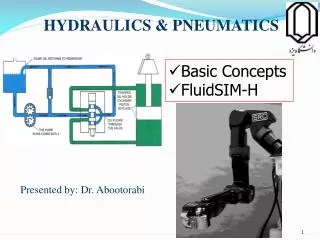
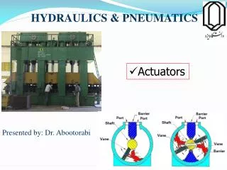
Vocabulary • Actuator • Alpha Stirling Engine • Beta Stirling Engine • Constant volume process • Displacer piston • Gamma Stirling Engine • Flywheel • Force multiplication • Heat exchanger • Heat sink • Hydraulics • Isothermal • Linear motion • Master piston • Mechanical advantage • Pascal’s Law
Vocabulary, cont. • Piston • Pneumatics • Power piston • Pressure chamber • Regenerator • Rotational motion • Slave piston • Stirling Engine
Stirling Engines • A Stirling engine is a heat engine that operates by expanding and compressing a working fluid, usually a gas-like air, in a cyclical fashion. • A Stirling engine has the following components: • Heat source • Hot side heat exchanger • Regenerator • Cold side heat exchanger • Heat sink • Displacer piston • Power piston
Types of Stirling Engines Alpha Stirling Engine Beta Stirling Engine Gamma Stirling Engine Beta Stirling engine Alpha Stirling engine Gamma Stirling engine
Beta Stirling Engine Steps • Isothermal expansion • Constant volume heat removal • Isothermal compression • Constant volume heat addition • . 2. 1. 4. 3.
Build Your Own Stirling Engine • Using the materials and instructions provided, construct Stirling engines in teams. • Record the temperature every 15 seconds for 5 minutes. • Calculate the kinetic energy of the flywheel and the heat energy added to the system. How do these compare? What is the efficiency of this engine with regards to transferring heat energy to rotational mechanical energy? • How else could you imagine heating the pressure chamber? • Building a Stirling Engine
Questions/Discussions • What type of Stirling engine was created in the video? Identify the components. • Draw and identify the different parts of the Stirling engine cycle for this engine. • What are the design features of this engine that affect the thermal efficiency? How could you improve them?
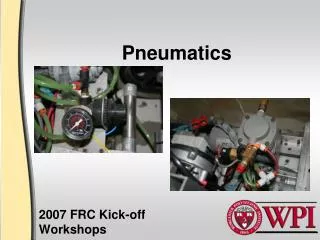
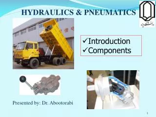
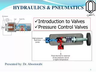
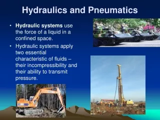
Pneumatics and Hydraulics • Pneumatics is a branch of engineering that harnesses the potential energy in pressurized gas to create mechanical motion. • Hydraulics is the branch of engineering that uses pressurized liquids to create mechanical motion. Pneumatic Aluminum Can Crusher Medical Applications of Fluid Power National Fluid Power Association (NFPA)
Pascal’s Law • The pressure exerted anywhere in a mass of a confined liquid is transmitted equally in all directions throughout the liquid without the pressure being diminished. • This is represented by the following equation:
Hydraulic Force Multiplication How Fluid Power Works
Hydraulic Force Multiplication Example Piston 1 = Master Piston Piston 2 = Slave Piston If r1 = 4 cm and r2 = 8 cm, then MA = 4. What would the MA be, if Piston 2 was the Master Piston?
Evaluate Hydraulic Force Multiplication • Using the materials and instructions provided, construct the four hydraulic systems as directed in the activity procedure. • Test each assembly by adding weights to the metal plate. When the syringe can no longer support a weight, the slave plunger will depress after the master syringe raises it. Record the weight at which this happens for each assembly. • Calculate the force multiplication factor for each assembly system. Compare the trend in force multiplication factors to the trend in the maximum weight each assembly held. • How do these trends compare? Does your data make sense?
Questions/Discussions • Assuming you applied the same force to the master 12 cc syringe in each trial, which syringe had the most force applied to it? • Which had the least? • How could you use this principle to do work in the real world?
Linear Hydraulic Motion • Linear hydraulic motion is created by attaching the end of a slave piston to an actuator that can only move in one direction. • When the master piston is depressed, the slave piston will drive the actuator linearly in one direction. • Three linear hydraulic assemblies can be combined to give motion along the x, y, and z axes. NFPA Hydraulic Motion Instructions
Rotational Hydraulic Motion • Rotational hydraulic motion is created by attaching the end of a slave piston to one side of an actuator that is attached to a wheel. • It is important that the end of the slave piston is attached away from the center of the wheel. • When the master piston is depressed, the slave piston will drive the actuator, which translates the force to the wheel. This force causes the wheel to turn.
Lifting Hydraulic Motion • Lifting hydraulic motion is created by attaching the end of a slave piston to an actuator that is hinged. • It is important that the end of the slave piston is attached away from the actuator’s hinge. • The closer the piston is to the hinge, the more height the actuator arm can achieve.
Lifting Hydraulic Motion, cont. • If there is a weight on the end of the arm, more force will be needed to lift the weight. • The farther away the piston is from the end of the arm, the more force is needed to lift the weight.
Building Hydraulic Systems • Using the materials provided, construct linear, rotational, and lifting hydraulic systems. • Identify the slave and master pistons in each assembly. Test each assembly by adding water to the systems. Next add a small amount of weight to the actuators. What happens? • Try combining your rotation and linear systems. Is it possible? What sort of motion is created? • Linear, Rotational, and Lifting Hydraulic Systems Instructions
Questions/Discussions • How could you use the principles of force multiplication and/or a system redesign to enable the three hydraulic systems to translate more weight? • Sketch a design of a system that uses at least one of each type of hydraulic system. What does your system do? • Choose a design from the class that would be possible to build with the number of systems currently in the room, then build it. • Discuss the hardest part of the process.
Hydraulic Arm Design Challenge • In teams of 2-3 students, you will • use your knowledge and experience gained in the previous activities to build a hydraulic arm, and • prepare a 45-minute presentation of your hydraulic arm to the class.
Criteria for Your Hydraulic Arm • The hydraulic arm must be able to lift an object over a wall 20 cm high and place the object on the other side within the designated area 15 cm from the wall. • The arm will be secured to the testing table with a vise, so each arm must have a base that allows it to be clamped to the table. • The arm can only be constructed from the given materials and have at least hydraulically controlled joints.
Credits • ClipArt; http://www.clipart.com/en/ • Images; http://commons.wikimedia.org/wiki/Main_Page • Slide 11 Alpha Stirling Engine video; from YouTube user; GREENPOWERSCIENCE; http://www.youtube.com/watch?v=5pdqDQwehlk
Credits, cont. • Slide 11, cont. Beta Stirling Engine video; from YouTube user; PullTab; http://www.youtube.com/watch?v=rr8g62rM7dM&feature=fvwrel Gamma Stirling Engine video; from YouTube user; Sawerrt; http://www.youtube.com/watch?v=UvrBzwBIFhM Gamma Stirling Engine graphic http://www.mpoweruk.com/stirling_engine.htm
Credits, cont. • Slide 13 Building a Stirling Engine video; from YouTube user; Jim Larsen; http://www.youtube.com/playlist?list=PL2AB1028849E86CC4&feature=plpp • Slide 15 Pneumatic Aluminum Can Crusher video; from YouTube user; Kedge24 http://www.youtube.com/watch?v=MpgrDgFz-RA Medical Applications of Fluid Power video; from YouTube user; National Fluid Power Association; http://www.youtube.com/watch?v=GWJJYH50wvM
Credits, cont. • Slide 15, cont. National Fluid Power Association (NFPA) YouTube Channel video; from YouTube user; National Fluid Power Association; http://www.youtube.com/user/natlfluidpowerassn?feature=results_mainraulics.aspx • Slide 17 How Fluid Power Works video; from YouTube user; CCEFP; http://www.youtube.com/watch?v=zZ0WwZcRrV4