Download
1 / 45
780 likes | 1.69k Views
Finite Elements and Fracture Mechanics. Leslie Banks-Sills The Dreszer Fracture Mechanics Laboratory Department of Solid Mechanics, Materials and Systems Tel Aviv University. ISCM-1 5 , October, 2003. Outline. Introduction to fracture mechanics (homogeneous material).

E N D
Finite Elements and Fracture Mechanics Leslie Banks-Sills The Dreszer Fracture Mechanics Laboratory Department of Solid Mechanics, Materials and Systems Tel Aviv University ISCM-15, October, 2003
Outline • Introduction to fracture mechanics (homogeneous material). • The finite element method. • Methods for calculating stress intensity factors. • Interface fracture mechanics.
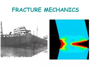
Liberty Ships-World War II • The hulls of Liberty Ships fractured without warning, mainly in the North Atlantic. • There were 2,751 Liberty Ships manufactured between 1941- 1945. Cracks propagated in 400 of these ships including 145 catastrophic failures; only 2 exist today which are sea- worthy.
Liberty Ships-(continued) • The low temperatures of the North Atlantic caused the steel to be brittle. • These are the first ships mass produced with welds. • Fractures occurred mainly in the vicinity of stress raisers. • The problem may be prevented by employing higher quality steels and improvement of the design of the ship.
The Aloha Boeing 737 Accident On April 28, 1988, part of the fuselage of a Boeing 737 failed after 19 years of service. The failure was caused by fatigue (multi-site damage).
m = I, II, III i, j=1, 2, 3 mode I mode II mode III Modes of Fracture
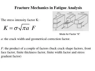
units Stress Intensity Factor m = I, II, III
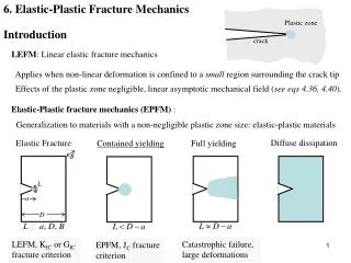
Fracture Toughness ASTM 399 Standard compact tension specimen material parameter, depends on environment
J -- integral strain energy density tractions J is a conservative integral
The Finite Element Method For a static problem:
The Element Lagrangian shape functions for a four noded element
The Element (continued) isoparametric element
Special Crack Tip Elements quarter-point elements Henshell and Shaw, 1975, quadrilateral elements Barsoum, 1974,1976, triangular elements
Special Crack Tip Elements quarter-point elements Henshell and Shaw, 1975, quadrilateral elements Barsoum, 1974,1976, triangular elements
Special Crack Tip Elements quarter-point elements Henshell and Shaw, 1975, quadrilateral elements Barsoum, 1974,1976, triangular elements
Special Crack Tip Elements quarter-point elements Henshell and Shaw, 1975, quadrilateral elements Barsoum, 1974,1976, triangular elements
Eight Noded Isoparametric Element shape functions
Eight Noded Isoparametric Element shape functions (continued)
Square-Root Singular Element Banks-Sills and Bortman (1984)
Methods of Calculating KI • Direct Methods • Stress extrapolation • Displacement extrapolation • Indirect Methods • J – integral • Griffith’s energy • Stiffness derivative
Displacement Extrapolation (continued) for plane strain
J -- integral strain energy density tractions J is a conservative integral
Auxiliary Solutions solution (2a) solution (2b)
Interface Fracture Mechanics (continued) phase angle or mode mixity energy release rate
(1) (2) M – integral
Auxiliary Solutions solution (2a) solution (2b)
Summary • Accurate methods have been presented for calculating stress intensity factors based on energy methods. • The best methods are the area J –integral, stiffness derivative and area M –integral for mixed modes and interface cracks. • The J and M – integrals can be extended for thermal stresses, body forces and tractions along the crack faces. • Conservative integrals have been derived for homo- geneous notches and bimaterial wedges including thermal stresses. • Student wanted for extending these methods to piezo-electric materials