Download
1 / 33
480 likes | 3.44k Views
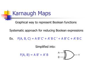
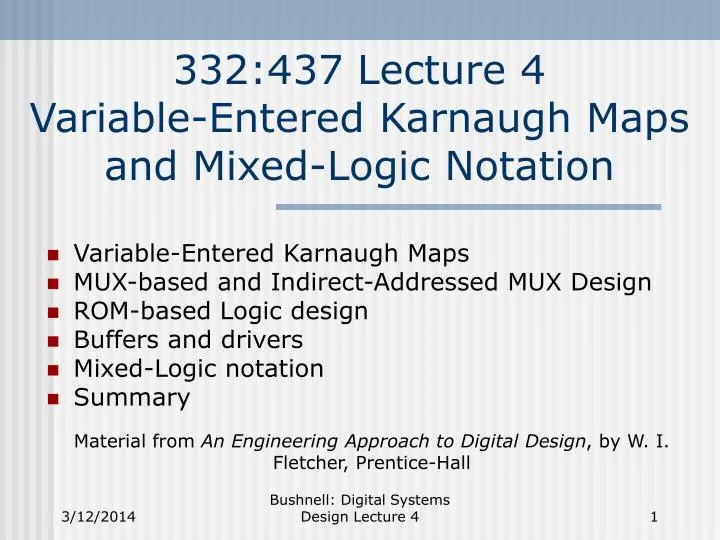
332:437 Lecture 4 Variable-Entered Karnaugh Maps and Mixed-Logic Notation. Variable-Entered Karnaugh Maps MUX-based and Indirect-Addressed MUX Design ROM-based Logic design Buffers and drivers Mixed-Logic notation Summary.

E N D
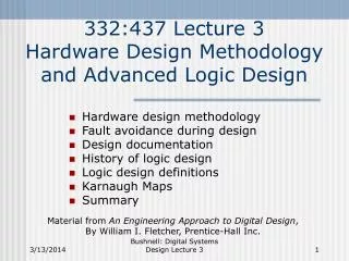
332:437 Lecture 4Variable-Entered Karnaugh Maps and Mixed-Logic Notation • Variable-Entered Karnaugh Maps • MUX-based and Indirect-Addressed MUX Design • ROM-based Logic design • Buffers and drivers • Mixed-Logic notation • Summary Material from An Engineering Approach to Digital Design, by W. I. Fletcher, Prentice-Hall Bushnell: Digital Systems Design Lecture 4
Variable-Entered Karnaugh Maps (VEM) • Allow 8 to 16 variable maps to be represented as 3 to 5 variable maps • Needed because typical Boolean design problem involves 8 or more Boolean variables Bushnell: Digital Systems Design Lecture 4
AB CD 00 01 11 10 00 1 00 1 00 1 00 1 11 1 1 11 11 1 1 11 01 01 1 1 1 1 01 1 1 1 1 01 10 10 10 1 1 10 1 1 AB CD 00 01 11 10 AB CD 00 01 11 10 Six-Variable K-Map AB CD 00 01 11 10 EF = 00 EF = 01 EF = 10 EF = 11 Bushnell: Digital Systems Design Lecture 4
Variable-Entered Map (VEM) • Conventional logic minimization: • Time consuming • Error-prone • VEM Key idea: • Represent values of function in terms of its variables (called map-entered variables) within Karnaugh map framework • Group like variables in Karnaugh map cells Bushnell: Digital Systems Design Lecture 4
Map Entry 0 c c c + c or 1 X Situation No minterms with this condition f = 1 when c = 0 f = 1 when c = 1 f = 1 when c = 0 or 1 f = X (don’t care) Example VEM f (a, b, c) = a b c + a b c + a b c + a b c Arbitrarily choose c as map entered variable Bushnell: Digital Systems Design Lecture 4
ab c 0 1 00 1 0 01 0 1 11 0 1 10 1 0 XOR/XNOR Gate Grouping • New way of grouping map variables • For this example: • f = c b Bushnell: Digital Systems Design Lecture 4
a b 0 1 c 0 c c 1 c + c 0 f b a Example Result • VEM technique reduced an ordinary 3-variable K-map to a 2-variable map • Must group only like minterms in VEM • f = c ( b ) + c (a b) Bushnell: Digital Systems Design Lecture 4
ab c 0 1 00 1 0 01 0 1 11 0 0 10 1 1 a b f c Conventional K-Map Method • f = (c b) a + a b Conventional Way VEM Way # 2-input gates 4 4 # inverters 2 0 Bushnell: Digital Systems Design Lecture 4
Use of DeMorgan’s Theorems to Transform Logic Gates Bushnell: Digital Systems Design Lecture 4
VEM Techniques • Use as many map-entered variables as you like • Works well for partially-minimized functions – use remaining variables as map-entered variables. • Example • f (w, x, y, z) = Sm (3, 4, 6, 7, 10) + Sd (9, 11, 12, 14, 15) • Choose w, x, y as ordinary K-map variables • Make z the map-entered variable • Only appears inside K-map entries Bushnell: Digital Systems Design Lecture 4
Example (continued) Map Entry 0 z z 1 z z + z X z X z X + z X w 0 0 0 0 0 0 0 0 1 1 1 1 1 1 1 1 x 0 0 0 0 1 1 1 1 0 0 0 0 1 1 1 1 y 0 0 1 1 0 0 1 1 0 0 1 1 0 0 1 1 z 0 1 0 1 0 1 0 1 0 1 0 1 0 1 0 1 f 0 0 0 1 1 0 1 1 0 X 1 X X 0 X X • Truth table Bushnell: Digital Systems Design Lecture 4
wx y 0 1 00 0 z 01 z z + z 11 z X z X + zX 10 zX z + zX Example (concluded) • Variable-Entered K-Map • f = y z + x z + w y z Bushnell: Digital Systems Design Lecture 4
MUX-Based Logic Design • Use circuit inputs to select from a variety of Boolean functions for the circuit output • Functions wired to MUX inputs • Often more efficient than SOP or POS design • Problem: Sometimes you need a 5-input MUX (32 different input function selections), but there are really only 5 distinctly different input functions • Wastes chip area with a large MUX • Solution: Indirect-addressed MUX Bushnell: Digital Systems Design Lecture 4
b X X X X X 0 0 1 c X 0 0 1 1 0 1 X All else e 1 0 0 0 0 X X X a 0 0 0 0 0 1 1 1 d X 0 1 0 1 X X X Z f g f g g h h f g 1 X Example Indirect-Addressed MUX-Based Design • Example truth table: Substitute ROM for MUX Bushnell: Digital Systems Design Lecture 4
A0 A1 A2 MUX Select f g f g g h h g 1 0 0 1 2 3 4 5 6 7 Z ROM and MUX Implementation ROM 000 001 001 010 010 011 011 100 100 001 101 110 000 A0 A1 A2 Word Address a b c d e 00001 to 01111 (odd only) 00000 01000 00010 01010 00100 01100 00110 01110 10000 to 10011 10100 to 10111 11000 to 11111 All others Bushnell: Digital Systems Design Lecture 4
ROM 1 1 0 1 1 1 1 1 a b c a 0 0 0 0 1 1 1 1 b 0 0 1 1 0 0 1 1 c 0 1 0 1 0 1 0 1 F 1 1 0 1 1 1 1 1 0 1 2 3 4 5 6 7 F Straight ROM Logic Implementation • Sometimes the best design method Bushnell: Digital Systems Design Lecture 4
a b F c Alternate Discrete Logic Implementation • May very well use as much chip area as ROM implementation – each ROM cell needs only 1 transistor Bushnell: Digital Systems Design Lecture 4
Logic Gate Choices • Extra unused inputs • Terminate properly by connecting to non-controlling logic value • OR/NOR/XOR – connect to 0 (Vss) • AND/NAND – connect to 1 (VDD through pullup resistor) • EQUIVALENCE – connect to 1 • Unconnected extra inputs act like radio antennas • Collect electrical noise & randomly fluctuate between logic 0 & 1 Bushnell: Digital Systems Design Lecture 4
Choice of Logic Realization • CMOS, nMOS, & TTL logic families • Fewer transistors in NAND/NOR gates than in AND/OR gates • NAND/NOR also faster than AND/OR • Gate substitution: Use 3-input AND gate instead of cascaded 2-input AND’s (faster) Bushnell: Digital Systems Design Lecture 4
Form Substitution • All 3 realizations are exactly the same, but the single NOR gate realization is better Bushnell: Digital Systems Design Lecture 4
t1 … t2 Buffers/Drivers • Buffers have more driving current than ordinary CMOS gates – used for large fanout gates (more than 8-10). • Do not load up an ordinary CMOS gate with more than 8-10 gates Delay = t1 + n t2 Delay = t1 + t2 Bushnell: Digital Systems Design Lecture 4
Collector Base Emitter Buffers/Drivers (continued) • Drivers – adapted for higher current & voltage levels than buffers • Examples: TTL CMOS, CMOS TTL conversions • Reason: TTL output I-V specification does not match analog circuit specification • Examples: relays, analog switches, fluorescent displays, appliance controls • High-Voltage Drivers • Usually have open-collector Bipolar outputs Bushnell: Digital Systems Design Lecture 4
Enable Buffers/Drivers (continued) • Line drivers – provide (source) large I or accept (sink) large I • Source: 40 mA with 50W load • Sink: 60 mA • For interface lines (long) between digital systems • Bus driver – Line Driver with tri-state output When disabled, goes into high impedance state at output Bushnell: Digital Systems Design Lecture 4
Buffers/Drivers (continued) • Line Receiver – actually a driver – used at receiving end of bus interface to latch & amplify signals sent over bus • Load on bus is single load – but signal amplified & sent many places Bushnell: Digital Systems Design Lecture 4
Logic Types • Positive Logic (active high) • 0 = 0 V., 1 = 1.0 V. • Negative Logic (active low) • 0 = 1.0 V., 1 = 0 V. • Mixed-Logic – logic with: • Negative (positive) logic inputs • Positive (negative) logic outputs • Arbitrary mixture of positive & negative logic • Most systems designed this way • Can be confusing Bushnell: Digital Systems Design Lecture 4
Mixed Logic Notation • Load Active high signal • /Load Active low signal • /Load = Load • Load = /Load Bushnell: Digital Systems Design Lecture 4
Multiple Gate Interpretations • Positive logic: Negative logic: Bushnell: Digital Systems Design Lecture 4
Why Do We Need Negative Logic? • Easier to hold unused inputs of circuit at high voltage level rather than at low voltage level • Hold many unused inputs high – only active ones need to be held low • Easier to label signals in terms of their functions whether or not data is positive or negative • Example: IN / OUT • Often get better noise immunity with negative logic than with positive logic • Particularly true on buses • Low hardware noise margin often better than high hardware noise margin Bushnell: Digital Systems Design Lecture 4
Mixed-Logic Design Rules • If an input (output) is negative, LABEL IT with / and make sure that it flows into (from) a bubble • If an input (output) is positive, DO NOT LABEL IT with / and make sure that it does not flow into (from a bubble) • Not always possible to follow these rules in every part of the circuit due to Boolean function Bushnell: Digital Systems Design Lecture 4
/A /C /B C A B Example • If A, B, C are negative logic, better notation: • Meaning: If A is turned on or B is turned on, then C is turned on • Negative logic has the OR operation, so the negative logic picture corresponds to that Bushnell: Digital Systems Design Lecture 4
Real-Life Circuit Design • Mixed-logic occurs most frequently • 2-level SOP or POS forms may use way too much hardware • Always true for very large circuits • Instead, use multi-level logic Bushnell: Digital Systems Design Lecture 4
/b /b a a f f c c d d Transformations • Can always add bubbles to both ends of a wire without changing circuit function • Turn AND-OR into NAND-NAND form Bushnell: Digital Systems Design Lecture 4
Summary • Variable-Entered Karnaugh Maps • MUX-based and Indirect-Addressed MUX Design • ROM-based Logic design • Buffers and drivers • Mixed-Logic notation Bushnell: Digital Systems Design Lecture 4