Download
1 / 25
250 likes | 426 Views
Installation. BXR-48000 Switch Router. Objectives. Perform site preparation Check and unpack the BXR-48000 switch router Install the BXR-48000 switch router Verify installation. Physical and Environmental Considerations. 21.25”.

E N D
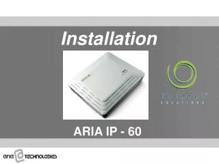
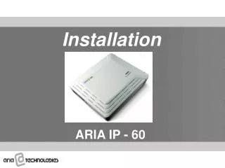
Installation BXR-48000 Switch Router
Objectives • Perform site preparation • Check and unpack the BXR-48000 switch router • Install the BXR-48000 switch router • Verify installation
Physical and Environmental Considerations 21.25” • Must install Chassis A to the right of Chassis B to connect the units properly • Requires four feet of clearance in the front of each rack if using both Chassis A and B for install and removal purposes • Requires rear DC power feed clearance since heavy duty DC cables are not as flexible as typical AC power cables • All fiber management is located on the front of the chassis 75.25” 24”
Power and Electrical Provisions • Power feed should be a 0 AWG wire • Three poles on each terminal block • N48RTN (Negative 48 ReTurN) • N48V (Negative 48 Volt) • Chassis GND (earth GrouND) • Acceptable range -36/-40 to –75V DC • Rack must be grounded
Concerns and Precautions Physical Security Concerns: • Access to the BXR-48000 must be controlled due to areas of vulnerability: • Serial port - unauthorized login • Modules - damage, deactivation, removal • Physical connections - damage or removal of alarm leads, timing, management and signal cables • Power source(s) - interruption, shorting Safety Precautions • Weight of the chassis • Power connections • Weight of the fan trays • Damage to waveguide • Electrostatic Discharge (ESD) concerns • Damage to backplane during card insertion • Damage to circuit boards from casual contact
Unpacking the Chassis • Crate can be handled two ways: • Horizontally - moved by fork truck or on casters • Vertically - moved on casters • Unpack from horizontal position • Instructions are located on the side of the crate
Removing the Lid of the Crate • In a horizontal position, remove the ten retaining clips • Remove the lid of the crate Removing the crate lid Removing the retaining clips
Lifting the Chassis • At least four people should assist in lifting the chassis • Two people should grasp the top of the crate and lift it towards two other people • Two people should steady the crate on the casters as it is lifted to an upright position • Use an Allen wrench (hex key) to open four rotary latches, two on each side on the short end of the container Opening rotary latches Lifting the Chassis
Removing the Crate from the Chassis • With a person on each side of the crate, lift it off the casters
Installing the BXR-48000 Switch Router • All hardware components are shipped in a separate box except for the card carrier which is pre-installed in the chassis Card Carrier
Step 1 - Connecting the Power Feeds • Remove the acrylic panel • Install all four groups of power feed cables • Reinstall the acrylic panel over power connections • Repeat process for chassis B
Step 2 - BITS Timing Connection • Remove the cover plate of Timing Interface Module (TIM) • Connect the timing source to either the modular jacks or the wire wrap pins • Replace the cover plate and feed the cable from the cut out hold of the cover plate • For proper ESD protection, a static discharge jack is located on the front of the chassis Cover Plate
Step 3 - Install Upper and Lower Fan Trays • Hold the upper fan tray on either side • Slide fan tray in place and verify it seats smoothly • Repeat procedure for lower fan tray • Verify fan filter is in place below the lower fan • Press the safety latches on both sides for fan removal Upper Fan Lower Fan Fan Filter
The proper ventilation is required: Above and below the chassis to allow proper fan exhausts Above the PCMs to allow fresh air intake Bottom to top airflow PCM have separate fans and airflow Air supply requirements 7,969 BTU/sec 478,125 BTU/min 28,687,504 BTU/hour Side View of Chassis REAR FRONT LowerCardCage Fan Tray Filter Chassisair intake Power air intake Power exhaust Ventilation Concerns
Step 4 - Load Power Conditioning Modules • Verify ejection lever is in the open position • Insert the PCMs into the bottom bays Ejection Lever
Step 5 - Power-up Test • Prior to installing logic boards, turn on all PCMs • Both fan trays should display green LEDs • Allow the power to run approximately five minutes while continuing to inspect the power connections • If no problems arise, power down PCMs
+ AIM Upper card cage Lower card cage Port card 12 Port card 0 TCM 1 Port card 13 Port card 14 Port card 15 Port card 1 Port card 2 Port card 3 Port card 17 Port card 5 Port card 18 Port card 6 Port card 19 Port card 7 Fabric 3 Fabric 6 Fabric 5 Fabric 2 Fabric 0 Port card 4 Port card 16 Fabric 1 Fabric 4 SCP 1 SCP 0 Port card 21 Port card 22 Port card 9 Port card 23 Port card 10 Port card 11 Port card 20 Port card 8 TCM 0 Lower card cage Step 6a – Prepare to Install Logic Boards (Chassis A)
+ Upper card cage Lower card cage Port card 36 Port card 24 Port card 37 Port card 25 Port card 26 Port card 38 Port card 39 Port card 27 Port card 40 Port card 41 Port card 29 Port card 42 Port card 30 Port card 43 Port card 31 Fabric 11 Fabric 8 Fabric 9 Fabric 12 Fabric 10 Blank Fabric 7 Port card 44 Port card 33 Port card 45 Port card 46 Port card 34 Port card 35 Port card 47 Lower card cage Port card 28 Port card 32 Step 6b - Prepare to Install Logic Boards (Chassis B) Blank Blank Port card 36a Blank
Install SCPs • Up to two SCPs • Optional SCP used for failover support • Far-right slots (labeled X and Y) • SCP boards are interchangeable • Bottom lever in locked ON position • Installed in Chassis A only Chassis A
+ Install Fabrics • Install fabrics beginning with lowest number slot • Use any fabric board; they are interchangeable • Fabrics must occupy contiguously-numbered slots starting with FP (redundant) or 1 (non-redundant) • Remember valid configurations: • 1, 2, 3, 4, 6 or 12 fabrics • Requires greater insertion force than other boards (extra large insertion/ejection handles)
Install TCM and AIM • The card carrier is pre-installed in the chassis • Populate card carrier with Alarm Interface Module (AIM) and Timing Control Modules (TCMs) • Installed in chassis A chassis A
Install Port Cards • Active port card slots are dependent on fabric configuration • The last boards require extra care due to the tight fit • Ensure all SCPs, fabrics and port cards have the hot-swap switch in the vertical position
Step 7 – Install Interconnect Cables Cable connector Wafer connector Interconnect cables
Step 8 – Power-up • Turn on the power to all PCMs • At a hardware level, fans and LEDs are the only indications available • Look for green LEDs on fan trays • Watch display LED on SCPs • Access serial port connection • System awareness must be checked through the user interface
Summary • Performed site preparation • Checked and unpacked the BXR-48000 switch router • Installed the BXR-48000 switch router • Verified installation