Download
1 / 19
190 likes | 321 Views
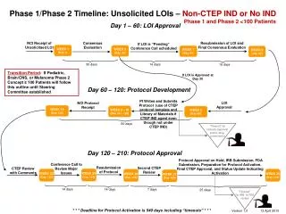
Second LHC Splice Review. Copper Stabilizer Continuity Measurement possible QC tool for consolidated splices. K. Brodzinski, Z. Charifoulline, G. D’Angelo, M. Koratzinos, J. Steckert, H. Thiesen, A. Verweij. H. Thiesen 28 November 2011. CSCM possible QC tool for consolidation splices.

E N D
Second LHC Splice Review Copper Stabilizer Continuity Measurement possible QC tool for consolidated splices K. Brodzinski, Z. Charifoulline, G. D’Angelo, M. Koratzinos, J. Steckert, H. Thiesen, A. Verweij H. Thiesen 28 November 2011
CSCM possible QC tool for consolidation splices • Outline • Project motivations and objectives • Tests description • Powering implementation • Circuit protection • Cryogenic issues • Main risks • Planning and impact • Conclusion H. Thiesen – 28 November 2011
Project motivations and objectives Conclusions of Steve Myers from Chamonix 2011: Recommendations of the 3rd MAC meeting: Recommendation: (R9) Launch the Copper Stabilizer Continuity Measurements Project aimed at the measurement of all the copper stabilizer joints in all the LHC sectors during the technical stop at the end of 2011. On the basis of these measurements the safe 2012 operation beam energy can then be determined. • The CSCM project was launched after Chamonix 2011 to identify for each main circuits (MB and MQ) the maximum safe current. • The main objective is a possible increase of energy in 2012. H. Thiesen – 28 November 2011
Test description • CSCM tests consist to reproduce similar conditions to those during a quench, but w/o energy storedin the magnets so that the thermal runaway can safely be stopped by an interlock process. • This is achieved by doing the test at a temperature of about 20K, so that the magnets are no longer superconducting and the current passes through the bypass diodesconnected to all main magnets. H. Thiesen – 28 November 2011
Test description • During the test the busbar segment voltages are measured to detect the runaway. • Maximum safe current of the circuit can be calculated with the time delay and the current level. time delay H. Thiesen – 28 November 2011
Limitationof CSCM • The CSCM does not measure the quality of each splice. It can only identify the worst one. Cool down CSCM tests yes Run away no Warm up Warm-up and repair is only needed if the current at which the machine will run is larger than the safe current deduced from the CSCM test. repair H. Thiesen – 28 November 2011 OK
What can the CSCM measure? • The CSCM can also measure: • All 13 kA current lead-busbar connections at the DFB • All bypass diode paths H. Thiesen – 28 November 2011
Test implementation • LHC has been designed to operate the main dipole and quadrupole magnets with super fluid helium at 1.9K. • CSCM requests to operate the main MB and MQ magnets with gaseous helium at 20 K. • Special cryogenic control to maintain the arc at 20K • Special powering configuration to inject 6kA in the circuits • Special protection system to protect the circuits during the powering tests • The new powering configuration and the circuit protection system have to be designed and commissioned as permanent systems H. Thiesen – 28 November 2011
Powering configuration • The voltage delivered by RB (190V) and RQ (18V) power converters are not enough for the CSCM tests: • 1.7 < Vdiode < 2 V at 20 K (assumption) Open circuit Short circuit Open circuit Short circuit RB circuit RQ circuits (in series) H. Thiesen – 28 November 2011 • Modification of actual RB power converter to obtain the requested voltage
Powering configuration • Modification of RB power converter CSCM configuration Normal configuration H. Thiesen – 28 November 2011 Tests in P-Hall with 4 W load Same modified power converter (RB) for the both circuits (MB and MQs)
Powering configuration • RB powering configuration • RQ powering configuration • Main challenge = How to control the current in the “diode circuits” ? • 5 bars have to be maintained in the cryostat to have 400V insulation voltage at 20K H. Thiesen – 28 November 2011
CSCM protection system • During the powering tests, the CSCM protection system have to protect: • Busbar segments • Current lead • Magnets H. Thiesen – 28 November 2011
CSCM protection system • Busbar protection system 1000 boards are in production and will be delivered in December 2011 H. Thiesen – 28 November 2011
CSCM protection system • Tests in SM18 • The busbar segment protection system has been tested in SM18 • 10 m of MQ busbar • 50 mm single-sided defect H. Thiesen – 28 November 2011
Special cryogenic condition • Requested cryogenic conditions can be provided with good stability and homogeneity over a sector length: ARC at 20 K and 5 bars, DFBs cooled with 20 K GHe to maintain the current lead at nominal condition (TT891A@50K) • Proposed cooling of DFBs have to be analyzed in more in details • Particularity of busbar interface between DFB/Q7 interface to be studied • Recovery after each powering test is estimated at 5 hours
CSCM main risks • CSCM tests • During the CSCM tests the main risks (extremely small) are to damage a splice, a diode, a magnet or a DFBA (current leads or splice). • Splice or diode are “easy” to repair (warm up, repair, cool down, CSCM tests) • Magnet is “easy” to replace if spare is available (warm up, replace, etc…). • DFBA is more complex to repair: must be transport to the surface. • Recovery • Important modification have to be done to realize the CSCM tests • The main risk is to do a mistake during the recovery • The risk can be mitigate to acceptable level by procedure for reconfiguration, test and (re)commissioning. H. Thiesen – 28 November 2011
CSCM planning • CSCM tests request time and resources s1 s2 • Brief estimation of time • 2 sectors in parallel • 2 weeks for preparation • 2 weeks for the tests • 2 weeks for the recovery and recommissioning s3 s4 18 weeks (4.5 months) to tests the LHC s5 s6 • Planning can be optimized to reduce the time at 3.5 or 2.5 months • Preparation time can be done in parallel with the other LS1 activities • But powering tests can be done only during the night • CSCM campaign requests resources: 8 to 10 tech. or Eng. s7 s8 H. Thiesen – 28 November 2011
CSCM planning • If CSCM tests must be realized after the consolidation of the splices: • The project have to be approved in March - April 2012 • Type test has to be realized in one sector at the beginning of the LS1 (6 weeks) • CSCM campaign has to be integrated in the LS1 H. Thiesen – 28 November 2011
Conclusion • CSCM tests can be used to qualify the LHC at 7 TeV after the splice consolidation: qualification of the splices, diode paths and current lead – busbar connections • CSCM tests require to modify several critical systems as QPS, 13kA-EE, PIC and PC: full re-commissioning (IST and powering tests) is mandatory. • Cryogenic conditions can be provided with good stability and homogeneity over a sector length but proposed cooling of the DFBs has to be analyzed in details. • CSCM tests will interfere with other LS1 activities • CSCM tests present some risks (extremely small): damage a splice or a DFB/CL can not be excluded • CSCM tests require time (2.5-3.5 months) and resources (8-10 technicians-Engineers) • Engineering challenges are being met and a test and simulation program is under way (validation of protection system, correlation between 20 K and 1.9 K, control of power converter) • No show stoppers found so far but there are some open issue as PC current control. H. Thiesen – 28 November 2011