Download
1 / 36
440 likes | 640 Views
Temperature Measurement. with the LM75 via I2C-Bus-Interface. Agenda. Overview architecture (Baumgart, Stickdorn) I2C-Bus and LM75 (Carel, Barnefski, Mehlich) The parallel interface (Müller, Böttcher)

E N D
Temperature Measurement with the LM75 via I2C-Bus-Interface
Agenda • Overview architecture (Baumgart, Stickdorn) • I2C-Bus and LM75 (Carel, Barnefski, Mehlich) • The parallel interface (Müller, Böttcher) • Programming the parallel interface and the C-Programm to control temperature measurement (Schmitz, Sprenger, Hoffmann)
Index • Overview architecture (Baumgart, Stickdorn) • I2C-Bus and LM75 (Carel, Barnefski, Mehlich) • The parallel interface (Müller, Böttcher) • Programming the parallel interface and the C-Programm to control temperature measurement (Schmitz, Sprenger, Hoffmann)
Overview Architecture INTRODUCTION
Agenda • Let‘s get a general idea • I²C-Bus • LM75-board
Let‘s get a general idea: • Temperature is fed into the PC with help of electronic devices. • There is a variety of possibilities. • We have decided to use the digital temperature sensor LM75 and to connect this with the PC via parallel interface. PC C-program parallel interface
The LM75-Board components --------------------------------------------------------------------------- • bidirectional printer cable, ... • SMD board • several SMD chip resistors • LM 75 • SMD LED (Light-Emitting Diode)
The Program • The data will be processed by the program. • Via the parallel port it gets all information. • The program is written in the C-programming language.
Index • Overview architecture (Baumgart, Stickdorn) • I2C-Bus and LM75 (Carel, Barnefski, Mehlich) • The parallel interface (Müller, Böttcher) • Programming the parallel interface and the C-Programm to control temperature measurement (Schmitz, Sprenger, Hoffmann)
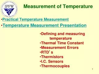
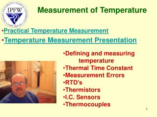
The LM75 • temperature sensor • analogue- to digital converter • digital over-heating detector • I2C interface. • The host can query the LM75 at any time to read temperature. • Over-heating shutdown becomes active when the temperature reaches a programmable limit.
Specifications • There are two types, the first one works with a supply voltage of 3.0V, and the second with 5.5V. • The maximum current is 1 mA, the typical value is 250 μA. • The LM75 detects the temperature.
Functional Description • The LM75 temperature sensor contains temperature sensor and a 9-bit Analog-to-Digital Converter. • The temperature data output of the LM75 is available at all times via the I2C bus. • The typical sequence is: • Stop condition: in order to reset the LM75 • Start condition: start signal • Addressing the LM75 if there are several available, selection • First temperature byte with integer part of temperature value • Second temperature byte (decimal places) • Stop condition
I2C BUS INTERFACE • I²C bus means announced “Internal Integrated Bus”. • Sometimes it also is called 2 wire bus (mass and supply tension not counted). • The first pipe is called SDA (= serially data). The real data are transmitted serially over these line. • The second pipe is called SCL (= serially clock). The time impulses are sent here.
Every I²C device can be selected via a 7 bit address. • The 8th bit indicates reading or writing. • Communication always takes place between a master and a slave. • In our case the PC is the master and the LM75 is the slave. • It doesn’t matter in which interval the transfer is done. It may take 7 days to transfer 1 Byte ;-)
Index • Overview architecture (Baumgart, Stickdorn) • I2C-Bus and LM75 (Carel, Barnefski, Mehlich) • The parallel interface (Müller, Böttcher) • Programming the parallel interface and the C-Programm to control temperature measurement (Schmitz, Sprenger, Hoffmann)
Definition • Via the parallel interface the Computer can communicate with external devices. • Data transmission is done simultaneously (8 bit parallel). • Often a printer is connected to the parallel interface. • Sometimes it is called Centronics interface.
Advantage & Disadavantage • Advantage: - quick transmission • Disadvantage - thick cable with limited length, higher costs
The parallel port All these pins correspond to the registers which are programmed by our software.
Components for parallel interfaces • The link between the periphery and the microprocessor used in the equipment is a component optimized particularly for this intended purpose, which mostly is called PIO (English: parallel input/ output) or • PPI (programmable peripheral interface). • Components for parallel interfaces are in many forms and variants.
Handshake Handshake is used to synchronize data communication
Register Addresses: • Data-Register (address 378): data output to the parallel if • Status Register (address 378+1): Printer can announce its status • Control-Register (address 378+2): Controls the interface
Index • Overview architecture (Baumgart, Stickdorn) • I2C-Bus and LM75 (Carel, Barnefski, Mehlich) • The parallel interface (Müller, Böttcher) • Programming the parallel interface and the C-Programm to control temperature measurement (Schmitz, Sprenger, Hoffmann)
LM-75 Application Software
Index of contents • General information on the LM75 • The program code • The main-routine • The While-operation • The temperature • Temp. Output
General information about LM-75 • Digital temperature sensor via LPT-interface • LM75 measures temperatures in an area from -55°C to +125°C • Temperature is retrieved via the parallel interface from the LM75 board with our program • Code is written in C • Base address is 0x378 (hex figure)
The Main-Routine • Deklaration of the variables • Screen-Messages • LED is switched off by an out-command • out (0x378, 0x00) means: the 0-byte is written in address 0x378 • LED is switched on for 3000 ms (sleep command) • LED is switched off
The while-operation • Closed loop: so this action is repeated endlessly • i2cstop: resets the i2c bus • i2cstart: attention command on the bus • the LM75 is adressed with address 10010001 (=0x91) • If the LM75 sends ACK, all is ok, otherwise (NACK) an error message is printed on the screen.
The Temperature • The temperature is written in the variable called cByte1 (i2clesen command) • If it´s successful, a positive ack is sent back to the LPT-interface • A second cByte is sent to get the decimal place • This is now saved in the cByte 2 • The i²c sends a not-ok ack back, to stop the data transfer
Temp. Output • Cbyte 1 & cbyte 2 are written in the fGradCelsius Variable • If there isn´t any mistake the program prints the exact room temperature on the screen. • In case of error the program produces an error message
… but his is not the end… now it is your turn…
Installing the Software • Install the UserPort.sys driver in the diretory windows\system32drivers\ • Start UserPort • Plug in the LM75 board into your parallel interface • Start lm75.exe