Download
1 / 10
600 likes | 1.9k Views
SHALLOW FOUNDATIONS. Spread footings Square Rectangular Circular Continuous Mat (Raft) foundations. SPREAD FOOTINGS. Made from reinforced concrete Square (B x B)-Usually one column Rectangular (B x L)-When large M is needed Circular (D/B<3, Rounded)-Flagpoles, transmission lines

E N D
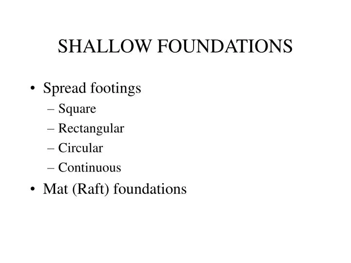
SHALLOW FOUNDATIONS • Spread footings • Square • Rectangular • Circular • Continuous • Mat (Raft) foundations
SPREAD FOOTINGS • Made from reinforced concrete • Square (B x B)-Usually one column • Rectangular (B x L)-When large M is needed • Circular (D/B<3, Rounded)-Flagpoles, transmission lines • Continuous (Strip)-Support of bearing walls • Combined (Cantilever)-Provides necessary M to prevent failure. Desirable when load is eccentric and construction close to property line.
MAT (RAFT) FOUNDATIONS • Necessary when the soil is weaker and more compressible • Since large area is needed from a spread footing, mat foundation is more economic. • Advantages • Spread the load in a larger area-Increase bearing pressure • Provides more structural rigidity-Reduce settlement • Heavier-More resistant to uplift • Distributes loads more evenly
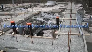
DEEP FOUNDATIONS • When shallow foundations cannot carry the loads • Due to poor soils conditions • When upper soils are subject to scour • Piles-prefabricated small-size (usually < 2 ft or 0.6 m diameter or side) poles made from steel (H or pipe piles), wood or concrete and installed by a variety of methods (driving, hydraulic jacking, jetting, vibration, boring) • Drilled shafts-Drilled cylindrical holes (usually > 2ft or 0.60 m in diameter) and filled with concrete and steel reinforcement
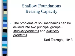
SHALLOW FOUNDATIONSBearing Capacity • Gross Bearing pressure q = (P+Wf)/A – u where Wf =gc*D*A, u = pore water pressure • Net Bearing pressure = Gross Bearing pressure –Effective stress • q = P/A + gc*D– u SQUARE FOOTINGS • q = P/(B*b) + gc*D– u CONTINUOUS FOOTINGS
SHALLOW FOUNDATIONSBearing Capacity (Cont’d) • FS bearing capacity = q ultimate / q allowable = 2 to 3 • q allowable= Gross bearing pressure • q ultimate = cNc +s’DNq + 0.5gBNg strip footing q ultimate = 1.3cNc + s’DNq + 0.4gBNgsquare footing q ultimate = 1.3cNc + s’DNq + 0.3gBNg circular footingf • See Table 17.1, page 623 for bearing capacity factors (Nc , Nq , Ng) as a function of friction angle, f. c = cohesion, s’D= vertical effective stress at foundation base level, D (surcharge), g=unit weight of soil below foundation base level, B=width (diameter) of footing • Effect of Groundwater table (Page 624) • Case1- DW < D (high water table; use buoyant unit weight) • Case2-D<Dw<D+B (intermediate water table; prorate unit weight) • Case3-D+B <Dw (Deep water table; use moist unit weight)
SHALLOW FOUNDATIONSDesign-Cohesive soils • End-of-construction (short term) analysis • Calculate q ultimate • q allowable = q ultimate /FS bearing capacity • Area allowable = P/ q allowable • Calculate setllement- d <d allowable- DESIGN OK d >d allowable- Consider soil improvement, deep foundation. Increasing area will not help, cause more settlement
SHALLOW FOUNDATIONSDesign-Cohesionless soils • Drained (long term) analysis • Calculate q ultimate Assume B to calculate q ultimate • q allowable = q ultimate /FS bearing capacity • Area allowable = P/ q allowable will give you B. Iterate until B assumed = B computed • Check if q allowable isOK for settlement case (usually at most 1 inch)
Deep Foundations Design • Static Analysis: Qultimate= QEB+QSR (end bearing + shaft resistance) QEB = qult Apwhere Ap is the area of pile tip qult = c Nc* + s’D Nq* QSR= SpLf where p=is the pile perimeter, L= pile length, and f = unit shaft resistance (skin friction) in a layer of soil on the side of the deep foundation f= K s’v tand + cawhere K=lateral earth coefficient, s’v = vertical effective stress at given depth, d=pile-soil interface friction angle, ca= pile-soil adhesion in a given soil adjacent to lateral pile surface • Pile load test, dynamic formulas, and wave analysis during driving are also used to arrive at a reliable pile capacity, Qu. • Qallowable = Qultimate /FS ; typically FS=2 for deep foundations.
Bearing Capacity Factors for Deep Foundations (Meyerhof, 1976)