Download
1 / 43
430 likes | 439 Views
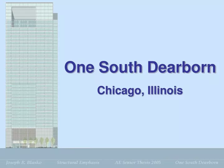
One South Dearborn. Chicago, Illinois. BUILDING INTRODUCTION. PRESENTATION OUTLINE. Building Introduction Existing Structure Problem Statement Proposal Structural Redesign Final Conclusions Recommendations Mechanical Study. BUILDING INTRODUCTION. Project Team. Owner

E N D
One South Dearborn Chicago, Illinois
BUILDING INTRODUCTION PRESENTATIONOUTLINE • Building Introduction • Existing Structure • Problem Statement • Proposal • Structural Redesign • Final Conclusions • Recommendations • Mechanical Study
BUILDING INTRODUCTION Project Team • Owner • Hines Interests Limited Partnership • Architect • DeStefano Keating Partners Limited • Structural Engineer • Halvorson Kaye Structural Engineers • Mechanical Engineer • Alvine & Associates, Inc. • Construction Manager • Turner Construction Company
BUILDING INTRODUCTION • One South Dearborn • 40 Stories • 1 Million sq. ft. • Modern High-Rise Commercial Office Building • Ground Floor • Retail Space • 3-Story Lobby • Floors 3-6 • Parking (160 Vehicles) • Floors 9-38 • Offices • Floors 2,7,8,39,40 • Mechanical
EXISTING STRUCTURE PRESENTATIONOUTLINE • Building Introduction • Existing Structure • Problem Statement • Proposal • Structural Redesign • Final Conclusions • Recommendations • Mechanical Study
EXISTING STRUCTURE • Structural Design Codes • Chicago Building Code • One South Dearborn • Composite Structural Design • Concrete Core • Perimeter Steel Floor Framing
EXISTING STRUCTURE Floor System • Steel Framing With Composite Steel Deck • 45’ Column-Free Spans • Yellow – Shear Walls • Green – Elevators • Corners Are Cantilevered Typical Framing High-Rise Plan
EXISTING STRUCTURE Foundation • Limited Underground Basement • Only The Core Descends Below Grade • Belled & Rock Caissons • Avoid Existing Caissons Previously On Site Enclosure • Pre-Cast Cladding – 90 psf • Supported On Perimeter Girders • Glass Curtain Wall – 20 psf • Supported From The Slab Edge
EXISTING STRUCTURE Lateral System • Reinforced Concrete Shear Wall Core • (2) Nonproportionate Shear Walls – N-S Direction • (3) Proportionate Shear Walls – E-W Direction • Provides All Lateral Strength & Stiffness Level 27 Thru P.H. Roof Foundation Thru Level 26
PROBLEM STATEMENT PRESENTATIONOUTLINE • Building Introduction • Existing Structure • Problem Statement • Proposal • Structural Redesign • Final Conclusions • Recommendations • Mechanical Study
PROBLEM STATEMENT • Local History & Material Tendencies • Influential Factors in Structural Design • Regional Preferences • Chicago • Past 20 Years, Composite System • Northeast • All-Steel Structural Systems • Southeast • All-Concrete Structural Systems
PROBLEM STATEMENT • Concerns About Current System • Differential Shortening • Plumbness Of The Wall • Phasing Of The Concrete & Steel Erection • Resulting Issues • Small Tolerances • Increase In Schedule Duration • Increase In Cost
PROPOSAL PRESENTATIONOUTLINE • Building Introduction • Existing Structure • Problem Statement • Proposal • Structural Redesign • Final Conclusions • Recommendations • Mechanical Study
PROPOSAL • The Existing System Was Chosen Due To The Owner’s Preferences. • Uninterrupted Floor Space • Perceptibility Of Lateral Motion • Ability For Future Modifications • Was This Really The Most Economical And Structurally Sound Choice When Compared To Other Conventional Systems?
PROPOSAL • Determine An Alternative Lateral System • Steel Braced Core and Outriggers • Determine An Alternative Flooring System • Post-Tensioned Concrete System • Determine The Impact These Changes Have On The Construction Schedule And Cost.
STRUCTURAL REDESIGN PRESENTATIONOUTLINE • Building Introduction • Existing Structure • Problem Statement • Proposal • Structural Redesign • Final Conclusions • Recommendations • Mechanical Study
STRUCTURAL REDESIGN Lateral System Redesign • Steel Braced Core & Outriggers • Several Iterations Of Different Configurations • Concentrically Braced Frames w/ and w/o Outriggers • Eccentrically Braced Frames w/ and w/o Outriggers • Worst Case Loading From Wind & Seismic Loads • WE Frames Concentrically Braced • NS Frames Eccentrically Braced • Freestanding Core • Minimum Size Members By Code
STRUCTURAL REDESIGN • Outriggers • Link The Core To The Exterior Columns – Truss • Increase The Effective Depth Of The Structure • By Adding A Level Of Outriggers • Increases Flexural Stiffness • Reduces The Overturning Moment • Tension In Windward Columns • Compression In Leeward Columns
STRUCTURAL REDESIGN • Engage The Interior Columns Of The Building • Enhances The System’s Ability To Resist Overturning • In Most Designs, The Gravity Columns Are Not Incorporated or Underutilized By The Outriggers • Floor Framing Plan Redesigned • To Utilize Interior Columns • To Accommodate The Changed Core • Constant Throughout Height Of Building • NS – 30’ Bays & WE – 25’ Bays
STRUCTURAL REDESIGN • After Solving For Member Sizes • Relative Stiffnesses Were Found • Torsional Eccentricity • 5% Of The Length Of The Building • Frames Redesign Under New Loading Condition • Allowable Drift • Chicago Building Code • H/750 - NS • H/600 – WE • To Maintain The Allowable Drift By Code The Members Were Oversized Dramatically
STRUCTURAL REDESIGN Drawbacks • Outriggers Interference w/ The Mechanical Space • A Set Of (2) 900 ton Cooling Towers Had To Be Moved Ten Feet To Clear an Outrigger On The 39th Floor • Diagonal Bracing • Inherently Obstructive To The Architectural Plan • Bracing Selected On Basis Of Allowing The Necessary Openings – e.g. Doors • At The Expense Of Efficiently Resisting Lateral Loads
STRUCTURAL REDESIGN Floor System Redesign • Post-Tensioned Concrete System • Wide Shallow PT Concrete Strips • Allows Long Spans • 3 Span Design • Oriented In The West-East Direction
Band Beam & Slab System Thickening Of The Slab Along The Column Line Allows Additional Drape Unbonded Tendon System Tendons Are Not Grouted Free To Move Independently Of The Concrete Easily Fixed To Different Profiles Easily Displaced Around Holes STRUCTURAL REDESIGN
STRUCTURAL REDESIGN • ADAPT-PT • Design 3-Span Condition • Core Strip • Column Strip • End Strip • Analyzed With Different Gravity Loads • Typical, Mechanical, Parking & Level 2
For Typical Office Loading Band Beam 96” Wide 11” Deep 6” Slab Spans 45’, Then 50’, Then 45’ Tendons ½” Diameter 27K – Final Effective Force 35 Tendons For Typical Design Strip Spacing Cannot Exceed 8x Slab Thickness or 5’ Mild Reinforcement Required Meet Factored Ultimate Conditions STRUCTURAL REDESIGN
STRUCTURAL REDESIGN • Partial Parabola Drape • Tendons Positioned Straight Over The Supports • Adjusting Drapes & Jacking Forces • Allowable Compressive & Tensile Stresses
STRUCTURAL REDESIGN • Deflections • Allowable By Chicago Building Code • L/360 • 45’ Span = 1.5” • 50’ Span = 1.67” • Will Not Be Discussed • Reinforced Concrete Shear Wall Core • Reanalyzed With Worst Case Wind & Seismic Loading • Including 5% Torsional Eccentricity • Column Design • Analyzed With PCA Column • Worst Case Moments & Axial Loading
FINAL CONCLUSIONS PRESENTATIONOUTLINE • Building Introduction • Existing Structure • Problem Statement • Proposal • Structural Redesign • Final Conclusions • Recommendations • Mechanical Study
FINAL CONCLUSIONS • Structural Redesign Criteria • Perceptibility of Lateral Motion • Uninterrupted Floor Space • Ability For Future Modifications • Maintain • Square Footage • Exterior Aesthetics • Story Height • Architectural Layout of The Building • Cost of The Structural System • Duration of The Structural System
FINAL CONCLUSIONS • Perceptibility of Lateral Motion • Steel Braced Core • Made Comparatively Stiff • Damping In The Range of 1% • Reinforced Concrete Core • Damping In The Range of 1.5% to 2% • Uninterrupted Floor Space • Ability For Future Modifications • Post-Tensioned Concrete • Limited To Minor Modifications • Flooring Depths
FINAL CONCLUSIONS • Cost Comparison • All-Steel Structure (18% Decrease) $3.32 Million • All-Concrete Structure (36% Increase) $7.87 Million • The All-Steel Structural System Is Significantly Less Expensive Than The Other Systems
FINAL CONCLUSIONS • Schedule Comparison • Existing Duration: March15, 2004 to February10, 2005 • All-Steel Structure (10% Decrease) 4 weeks • All-Concrete Structure (35% Increase) 10 weeks • The All-Steel Structural System Has A More Efficient Assembly Than The Other Systems
RECOMMENDATIONS PRESENTATIONOUTLINE • Building Introduction • Existing Structure • Problem Statement • Proposal • Structural Redesign • Final Conclusions • Recommendations • Mechanical Study
RECOMMENDATIONS • The All-Steel Structure Had A Lower Expenditure And Shorter Construction Phase • The Composite Structure Is The Better Solution • Composite Structure Made The Best Use Of The Materials And Their Respective Benefits • Concrete • Lateral Drift Control • Steel • Long Spans & Flexibility For Future Modifications
MECHANICAL STUDY PRESENTATIONOUTLINE • Building Introduction • Existing Structure • Problem Statement • Proposal • Structural Redesign • Final Conclusions • Recommendations • Mechanical Study
MECHANICAL STUDY Existing Mechanical • (2) 1500 Ton Chillers • 7th Floor • (4) 900 Ton Cooling Towers • 39th Floor • (4) 162,000 cfm Air Handling Units • (2) 7th Floor • (2) 39th Floor • 25,000 cfm Air Handling Unit • Lobby
MECHANICAL STUDY • Try To Lower Building Operating Costs and The Capital Cost of The Cooling Equipment • Thermal Energy Storage • Partial-Storage • Load-Leveling • Chillers Run At Full Capacity For 24 Hours • Demand-Limiting • Chillers Run At Reduced Capacity During On-Peak Hours Load-Leveling Demand-Limiting
MECHANICAL STUDY • Chicago, Illinois • On-Peak • 12 hours – 6AM to 6PM • 5.75¢/kwh • Off-Peak • 12 Hours – 6PM to 6AM • 2.49¢/kwh • Worst Design Month – July • Total Building Load – 28008 Ton-hrs • Peak Load – 2670 Tons • Ice Storage • 25% Ethylene Glycol Running Thru The Pipes
MECHANICAL STUDY • Load-Leveling • Chillers • (2) 760 Ton (Derated) • Storage Tanks • 19 Units • Monthly Savings • $1,238.72 (23% Savings) • Demand-Limiting • Chillers • 962 Ton • 540 Ton (Derated) • Storage Tanks • 24 Units • Monthly Savings • $1,521.91 (29% Savings) • Equipment Cost Greater Than Load-Leveling
MECHANICAL STUDY • Structural Impact • Storage Tanks – 391psf • Original Design – 250 psf • Redesign 7th Floor • Post-Tensioned Concrete Floor • 4” Deeper In The Band Beams • Additional $7,956 • Steel Floor Framing • 26 Tons Steel Added • Additional $423,330
ACKNOWLEDGEMENTS Professional Contacts My Family Penn State AE Faculty AE Class of 2005 Special Thanks To: Thesis Hard At Work
QUESTIONS What Would You Say, You Did Here? Look! I Already Told You. I Deal With The Customers So The Engineers Don’t Have To. I HAVE PEOPLE SKILLS!!! ?