Download
1 / 34
350 likes | 417 Views
This article explores the advancements in vacuum electronic devices (VEDs) for generating coherent radiation sources, including applications in military, commercial, and research sectors. The text covers topics like high-power gyrotrons, pulsed sources for high-power microwaves, folded waveguide amplifiers, and the use of VEDs in Stanford's LCLS and satellite communications. Furthermore, it delves into electron beam formation, beam-wave interactions, and various types of VED sources such as klystrons, traveling wave tubes, magnetrons, and cross-field amplifiers. Additionally, the importance of modeling and simulations in understanding, diagnosing, and optimizing experiments related to VEDs is highlighted, along with discussions on computational codes and simulation techniques, including steady-state trajectory codes, beam-wave interaction codes, and hybrid models.

E N D
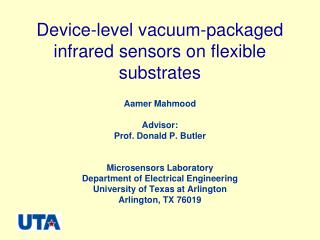
Advances in Vacuum Electronic Sources of Coherent RadiationThomas M. Antonsen Jr.Departments of ECE and PhysicsUniversity of MarylandApril 13, 2016
Vacuum Electronic Device (VED) a.k.a. a Tube Vacuum Tube amplifiers are favored by some audiophiles. They have a “warm” sound. Will be the subject of a plenary talk at IVEC 2016 IVEC = International Vacuum Electronics Conference
Who is that Audiophile? Professor Roy
Vacuum Electronic Devices Strong Suit Used in Military/Commercial/Research Applications High Power • 2 MW 170 GHz CW Gyrotrons for fusion plasma heating • Multi-GW 1 GHz pulsed sources for HPM “effects” • High Frequency • 220 GHz folded waveguide travelling wave amplifier • XFEL Stanford LCLS • High Efficiency • C-Band Helix TWT for satelite communications (> 60%) • SLAC Klystron
Driver (Amplifiers only) Energy recovery Generic VED Source Electron Beam formation Power out Static magnetic fields beam-wave interaction
Examples L3 Ka Band Power Module http://www.linkmicrotek.com Monica Blank 170 GHz CPI Gyrotron IEEE IVEC http://ieeexplore.ieee.org Experimental high power set-up showing the CPI 218.4 GHz EIK driving the compact NRL Serpentine Waveguide (SWG) TWT.
Current Modulation: DC AC Density modulation gridded tubes inductive output tubes Velocity modulation (O-Type) klystrons Traveling wave tubes Spatial modulation (M-Type) Magnetrons Cross field amplifiers Density modulation effective only for low frequencies due to grid capacitance
Velocity Modulation O-Type bunching power in power out Cavity 2 I(t) Cavity 1 Cavity 2 Field in cavity 1 gives small time dependent velocity modulation Fast electrons catch up to slow electrons giving large current modulation. Cavity 1
Helix Traveling Wave Tube (TWT) Klystron Coupled - Cavity TWT RF RF RF RF Out Out In In Interaction Interaction Depressed Depressed Circuit Circuit Collector Collector Electron Electron Gun Gun Electron Beam Electron Beam Impedance Impedance Extended Interaction Amplifier RF RF RF RF In Out In Out Interaction Depressed Depressed Sever Sever Circuit Collector Collector Electron Electron Gun Gun Electron Beam Electron Beam Interaction Circuit Impedance Impedance Different Classes of O-Type Devices
Synchronism in a Linear Beam Device Doppler curve kz vz Dispersion curve w (kz)
Beam Wave Interaction Simulations • Baruch Levush, Alexander Vlasov, Igor Chernyavskiy, Simon Cooke, John Pasour, George Stantchev, • Khanh Nguyen1, Edward Wright1 , • David Chernin2, John Petillo2 and Thomas Antonsen2 • US Naval Research Laboratory, Washington, DC • 1Beam Wave Research, Inc., Bethesda, MD • 2 Leidos Inc., Reston, VA • Work supported by the US Office of Naval Research
Apology: I am not really a computer expert. Computation
Why is Modeling and Simulation Important? • Understanding of basic physical processes • Understanding and diagnosing particular experiments • Designing improved experiments • Optimizing designs for “ first pass success”
Basic Code Types • Steady State Trajectory Codes - electron guns - depressed energy collectors • Computational Electromagnetics Codes - cavities - periodic structures • Beam-Wave Interaction Codes -parametric -PIC -hybrid
Approaches to Modeling Interaction Reality Parametric Models First Principles (PIC) • Many approximations - Synchronous interactions - Requires subsidiary calculations - Can Incorporate measured data • Computationally efficient • few approximations -high self fields -one calculation incorporates all physics • Computationally intensive Hybrid Models -Incorporates the Best features of the other two
3D Time Domain Electromagnetic Modeling The 3D Finite-Difference Time-Domain (FDTD) Algorithm • 3D FDTD is widely used for time-domain electromagnetic simulation in research… • Exploration of new concepts – changes to 3D geometry/topology are easily represented • Time-domain model can include non-linear physics and transient effects • Full electromagnetic beam-wave interaction predicts amplifier gain, instabilities Yee grid Simulation domain is subdivided into a 3D Cartesian grid of cells Electromagnetic field components are associated with the edges and faces of each cell Maxwell’s Equations are expressed as centered finite difference equations (in space and time) – and solved in time using an explicit leapfrog scheme centered difference
GPU Accelerated PIC Simulations NRL Code Neptune was created to target GPU simulation Based on existing algorithms – adapted for the GPU architecture • FDTD algorithm for electromagnetics (explicit time step) • Boris algorithm for particle time step, with charge-conserving current deposition NEPTUNE 13.7M cells, 1M particles Conformal representation of metal surfaces (accurate geometry discretization) CPU GPU CPU GPU Simulation speed (normalized to 6-core “Sandy Bridge” CPU)
< < L l wiggler < < L = v / < < L l l W helix gyro z c T = L / v > > 1 w w transit z Q 2 L p T = < < < < < < t v w w rise z 6 n sec < < 250 n sec < < 6 p sec < < 10 sec m Parametric Models Based on Multiple Time Scales Analysis • Separation in length scales FEL • Separation in time scales - gyrotron oscillator
e ( x ) b ( x ) w E ( x , t ) = i A ( z , t ) e ( x ) exp [ i ] + c . c . d y c rf e ( x ) b ( x ) w B ( x , t ) = i A ( z , t ) b ( x ) exp [ i ] + c . c . d y c rf ( ( k k ) ) w w ( k ) w z z z Parametric Approach Amplifier Model Fields found in separate calculation Phase Amplitude Determined by Parametric Code
¶ 2 i ¶ p 2 * + v + ( z ) A ( z , t ) = d x j e ( x ) exp [ – i ] g d × y g t z ^ ¶ ¶ U w g d q ¶ ¶ g = + v = v E + E × t z z rf sc ¶ ¶ 2 d t m c beam d y = k v – w z z d t Signal Amplitude Parametric Equations Particle Equations Ensemble of nonlinear trajectories sampling all phases
v > 0 t g v < 0 g Electrons T Radiation 0 L Spatial - Temporal Characteristics for Different Devices t Electrons oscillator amplifier T Radiation x z 0 L FEL
Saturation by Phase Trapping Phase Space
RF Input RF Output Collector Gun Example of Hybrid Approach: TESLA-CC Code RF Fields in cavities outside beam tunnel are found as a solution of equivalent circuit equations TESLA: Telegraphist’s Equations Solution for Linear beam Amplifiers Full solution of Maxwell’s equations rewritten as matrix telegraphist’s equations inside beam tunnel CL Equivalent Circuit Approach: Solve time dependent circuit equations • Electron beam modeling: • Solve 3D equations of particle motion in symmetric (2D) RF fields • AC and DC space charge effects are included • Realistic focusing magnetic fields • Initial beam particles distribution can be imported from a gun code (including spreads due to thermal effects) • Extensive diagnostics of beam dynamics
TESLA-FW Large Signal Code Use 3D Electromagnetic (EM) Codes for dispersion and EM field distribution Calculate electron beam properties using gun code Beam properties TESLA-FW NRL Code (Beam-wave interaction) • Separation of external structure region from beam tunnel region • Solve discretized circuit equations for fields external to beam tunnel • Relativistic 3D equations of electron motion • Reproduce full solution of Maxwell Equations inside the beam tunnel “Transmission line Model for Folded Waveguide Circuits”, T.M. Antonsen, Jr., et al., IEEE Trans. on Electron Devices, 60 (9), 2013. Color-coded EM field distribution Gun-code MICHELLE calculations of beam transport Results of dispersion and impedance fitting in TESLA-FW to match the given ANALYST data High accuracy (better than 0.1% in dispersion approximation and ~1% in impedance approximation) *http://web.awrcorp.com/Usa/Products/Analyst-3D-FEM-EM-Technology
z Compute Currents Induced in Gaps Integrate Beam Eqns of Motion in Gap Fields Compute Gap Voltages from Circuit Eqns Representation of a bunched beam Parametric Approach: CHRISTINE-FW • Circuit model: • Dispersion and impedance: • Current induced in circuit by bunched beam: • Beam model: • Fixed radius disks • ~20-30 per wavelength • Axial (z-) motion only • AC and DC space charge fields are included. Values for , L, c, and Z1 (and attenuation per cell) must be specified. Ys Ib Z0 L Iterative Self-Consistent Solution for the Gap Voltages and Particle Trajectories:
Sensitivity Study of G-Band NRL Serpentine/Folded Waveguide TWT Extra space due to brazing: extra rectangle of 1.5% of W size of SWS Trapezoidal shape with 5% difference on the top and on the bottom Top Beam tunnel off-set in Y direction Bottom Include all measured details BT alignment: (+x) z x (-x) Ø is 3.7% less Ideal Ø x y a2 N = 64 gaps W Shifted by 12.6% Ideal Symmetric As-Built a1 Approx SWG cross sectional profile Beam Tunnel Location “IN” “OUT”
Modeling of G-Band TWT Using Large Signal Codes Small Signal Gain NRL G-band SWG TWT CPI 218.4 GHz EIK, 5W Drive Curves Experimental high power set-up showing the CPI 218.4 GHz EIK driving the compact NRL Serpentine Waveguide (SWG) TWT. C.D. Joye, et. al. “Demonstration of a High Power, Wideband 220 GHz Serpentine Waveguide Amplifier Fabricated by UV-LIGA”, IVEC 2013.
Neptune Simulations of NRL G-Band SW TWT NRL 220 GHz Serpentine TWT amplifier (simulations performed using measured dimensions) Transfer curves Small Signal Gain Data 11.7kV 11.9kV Neptune 11.7kV 11.7kV K. T. Nguyen et al., “Design Methodology and Experimental Verification of Serpentine/Folded-Waveguide TWTs”IEEE T-ED Special Issue on Vacuum Electronics, 2014 Good Agreement between Neptune predictions and measurements
NRL-CPI Ka-Band Power Booster TWT • Driver (CC-TWT): • Output power limited by drive-induced oscillation (DIO) • Booster (FWG-TWT): • Advantages over CC-TWT • Easier broadband matching – increased margin of stability FW Booster ~3-5 dB gain @ sat CC-TWT Driver + FW-TWT Booster RF Out RF In RF input 70 mW 38 cm 20 cm CC-TWT Driver ~40 dB gain @ sat Goal: Power Bandwidth ~ 2 kW x 5GHz B. Levush, IVEC 2014
Conclusions • Varity of design codes suitable for accurate prediction of operation of millimeter wave amplifiers has been developed, verified and validated recently in NRL: • Fast parametric 1D code CHRISITINE-FW • Hybrid 2.5D code TESLA-FW • Accelerated GPU based PIC code Neptune • NRL beam-wave interaction codes together with gun/collector design code MICHELLE (Leidos/NRL) and commercial 3D electromagnetics (ANALYST, HFSS) and magnetostatic (MAXWELL) codes are providing opportunities for: • Design Improvement • New optimized design • Tolerance analysis • First cut success design
History of Parametric Models • Linear beam devices (TWTs) • Numerical models
History (continued) • Gyro devices • Mode competition
History (cont.) • Free electron lasers