Download
1 / 41
410 likes | 594 Views
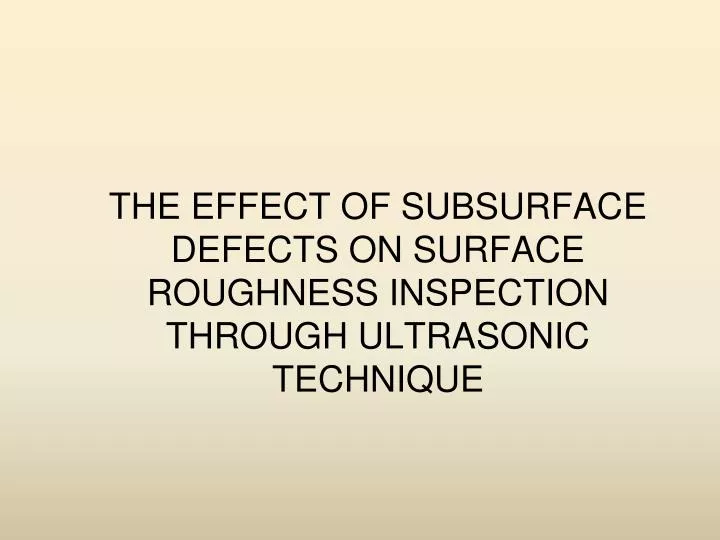
The effect of subsurface defects on surface roughness inspection through ultrasonic technique. Objective. To study the effect of sub surface defects in surface roughness monitoring through ultrasonic flaw detector. To study the sizing of defects. Ultrasound Concepts.

E N D
The effect of subsurface defects on surface roughness inspection through ultrasonic technique
Objective • To study the effect of sub surface defects in surface roughness monitoring through ultrasonic flaw detector. • To study the sizing of defects.
Ultrasound Concepts • All sound waves, whether audible or ultrasonic, are mechanical vibrations involving movement of the medium in which they are traveling. A sound wave may be transmitted through any material which behaves in an elastic manner. • Ultrasonic waves are classified on the basis of the mode of vibration of the particles of the medium with respect to the direction of propagation of the waves, namely longitudinal, transverse, and surface waves.
Ultrasound Concepts, cont., • A longitudinal stress wave propagates or traveling through coupling medium and touches surface of the engineering work piece will lose the energy due to attenuation. • There are three basic reasons for loss of energy, namely beam spreading, absorption, and scattering.
Ultrasound Concepts, cont., • The surface roughness of work piece attenuates the ultrasound waves and this scattering is a measure of surface roughness. • This behavior can account for a loss in amplitude of ultrasonic waves. • Such energy loss of the ultrasonic waves can be correlated with surface roughness of work piece which is machined by grinding process.
WORK DONE 1.The roughness is conventionally measured by roughness profilometer (Surfcorder). • For test piece A=0.7944 • For test piece H=9.5818
2. Artificial defects are made by drilling side holes as sub surface defects. • Defects are made in subsurface (3 mm) by drilling with different diameter (8mm, 6.5mm, 5mm & 4mm) drill bits.
3. Experiments are conducted in two modes 1.Contact test 2.Non-contact test(Immersion test)
1.Contact Test: Contact test is made by placing the probe on the test piece with couplant.
2.Non-contact test(Immersion test): • Test piece is placed in the couplant tank. • Testing is done by placing the probe on the top of couplant level. • Placing of probe is important in this method. Probe should be parallel to the couplant level, otherwise the ultrasonic waves will not propagate properly.
5. Feasibility of the online experiment is studied. • Here water is used as both coolant (grinding wheel) and couplant (ultrasound probe).
RESULT AND ANALYSIS
Contact test For test specimen H
From this graph, when the defect size increases the amplitude of the output signal increases because it provides plane for reflection with increase in defect size.
From this graph, the amplitude of the signal varies for the same size of defects. This due two reasons. 1. Due to irregular surface of the test piece, the amount of signal transmitted into the test piece is reduced. 2. Due to irregular surface area of the test piece, the perfect flow of couplant is not possible. This will reduce the amount of energy transmitted into the test piece.
Using this polynomial fit of roughness and amplitude, the roughness value of the material can be predicted when the amplitude is known with given ultrasonic parameters for mild steel.
For test piece A, at locations where there are no defect, the reflected amplitude signal maintained between the amplitude range of 79-84%(4%). • For test piece H, at locations where there are no defect, the reflected amplitude signal maintained between the amplitude range of 51-61%(9%). • These variations in amplitude for both the test piece is due to change in surface integrity at various locations. Hence these amplitude ranges can be used to calculate surface roughness for respective material.
The large variation in test piece H compared to test piece A is due to fact that the test piece H (Ra=9.5818) has roughness more than test piece A (Ra= 0.7944)
From the above attenuation co-efficient graph, when the defect size increases the attenuation co-efficient also decreases. It indicates that the amount of energy scattered from the test piece decreases. • Therefore, the attenuation co-efficient is indicator for the amount energy transmitted from the test piece due to defect.
Results of Frequency-Domain Analysis • The graphs amplitude Vs frequency given by MATLab software are given below
Frequency graph for rough surface-location1 Frequency graph for rough surface-location 2
Frequency graph for 8mm hole Frequency graph for 6.5mm hole
Frequency graph for 5mm hole Frequency graph for 4mm hole
From the the frequency ranges between 0.5 to 5 MHz which are inspected for rough surface. While from the other graphs the frequency ranges between 2.5MHz to 5 MHz which are inspected with holes of sizes 8, 6.5, 5 and 4mm. • The wide frequency range (0.5 to 5MHz) for rough surface is due to surface integrity on the surface. The signals are scattered much from the rough surface so there is a wide range of frequency.
When the defect size increases the amplitude of the output signal also increases. • For the same defect size, the reflected signal amplitude will vary according to the changes in roughness. Therefore, roughness is affecting the ultrasound wave transmitted through the test piece. Hence, measurement of roughness of the test piece is possible.
Attenuation co-efficient decreases with the increase defect size. • In frequency domain analysis, the frequency range for rough surface is wider than the defect area. So this concept helps to identify the rough surface from defect area
An effective and sensitive online inspection setup can be proposed for roughness measurement and defect location. Further it can save time, money and improve the quality of the resultant product