Download
1 / 15
150 likes | 298 Views
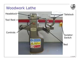
An Axtrusion Based Lathe. Roger Cortesi. Purpose: To design the most accurate lathe possible wit the Axtrusion prototype hardware and minimal other components. High Level Functional Requirements. Use Axtrusion prototype hardware Require a minimal of donated equipment

E N D
An Axtrusion Based Lathe Roger Cortesi
Purpose:To design the most accurate lathe possible wit the Axtrusion prototype hardware and minimal other components.
High Level Functional Requirements • Use Axtrusion prototype hardware • Require a minimal of donated equipment • Easy to assemble and test on granite surface plate • As accurate as possible while meeting above constraints
Axtrusion Prototype Hardware One Axtrusion carriage has been assembled and tested A second granite way has been built. A second carriage casting is available. It has not been machined
Initial Machine Concepts The first concept show with the tool closest to the work piece (top) and furthest from the work piece (bottom). Motion error estimates were performed for the tool in both positions. Moving the tool to the furthest from position added about 4 microns of error in the X and Z directions. Two more concepts that require that the ways be secured on a surface plate.
Spindle Selection • The workpiece spindle will have to be donated (or built by students). • Therefore our choices are limited in this matter. • For the initial machine design I arbitrarily selected a mid sized belt driven spindle from Setco™. • This seemed to be a representative sample of the spindles that would be available to us.
Data Used in Motion Error Model Carriage Error Data is from the Axtrusion Prototype. Roll data is estimated by removing errors due to the linear motor from the pitch and yaw data. The remaining errors are due to way straightness. These errors should be similar among pitch, yaw, roll. The sketch to the left shows how spindle Abbe error is estimated from the spindle runout data. The value for runout is applied in opposite direction at the front and rear bearings. This yields a formula for the angular displacement of the spindle centerline of:
Estimated Motion Errors 2 1 3 1a Values for “w/o grinding” have the errors associated with the tool spindle removed. Accuracies above are in microns and DO NOT include Thermal and Dynamic Errors.
Minimizing Thermal Errors • To fit the linear motor on the prototype carriage the cooling coils were remove. • The linear motor coil is a major heat source in the machine. • The carriage structure is magnesium with an a of • All these factors require that the “thermal centerline” of the Axtrusion carriage be used
Axtrusion Carriage Thermal Centerline The location of the thermal centerlines for the Axtrusion carriage is determined by the location of the way surfaces and location of the position encoder for the carriage. Locating Tooling, Spindles etc. on these centerlines will minimize thermal errors.
Improved Thermal Concepts The initial machine concepts are modified to improve their thermal performance. This concept is improved by moving the grinding spindle to the thermal centerline of its carriage. This concept improves its thermal performance by moving the tool post to the thermal centerline of its carriage. This action moves the tool tip away from the yaw COM, therefore greater error motions would occur.
Dynamic Errors Cutting forces on the machine are amplified by the Q factor when the machine is operating at resonant frequencies to form a much greater dynamic forces. These dynamic forces are then applied as static force to the machine and resulting displacements calculated and entered as the dynamic errors for the machine. 34 N is estimated to be the dynamic cutting forces on the machine. This is for finish cut on a 12mm diameter Aluminum part at max surface speed Calculation next slide… Modal Data from the Prototype Axtrusion Carriage
Tool Force Lt Lb 2 Air Bearings Center of Stiffness 2 Air Bearings Quick Check of Carriage Compliance Under the Estimated Dynamic Cutting Force So as an estimate these dynamic errors will add about 3 to 5 microns in each direction.