Download
1 / 21
210 likes | 343 Views
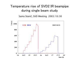
Beampipe design. F.Raffaelli. Framework for Geant4 Interaction Region simulation. G.Calderini, M.Marchiori, M.Mazur, E.Paoloni . 1) Beampipe design. F.Raffaelli. Some figures of merit. Power dissipation 1 KW Beam Pipe Radius O(1 cm) T Inlet 8 C T MAX raise 3 C

E N D
Beampipe design F.Raffaelli Framework for Geant4 Interaction Region simulation G.Calderini, M.Marchiori, M.Mazur, E.Paoloni
1) Beampipe design F.Raffaelli
Some figures of merit Power dissipation 1 KW Beam Pipe Radius O(1 cm) T Inlet 8 C T MAX raise 3 C Water speed < 5m/s Negative pressure
A possible design Pipe Inner Radius 1 cm “Uniform” Water Jacket (8 flat channels) Single channel area = 2.35 mm2 Channel width = 300 um To dissipate 1KW with water specific heat and thermal conductivity Peek (plastic) jacket Requires channel 1-side coating to prevent erosion (7um Ni and/or BerylCoatD) Flow: 4.2 m/s (OK)
Gold foil 4 um 0.121 % X0 Berillium 300 um 0.085 % Peek layer 500 um 0.142 % Water 300 um 0.083 % Ni coating 7 um 0.050 % Total 0.481 % X0
For comparison: BaBar: R= 27.9 mm SuperB R=10 mm (32mm Layer1) Total material 1.1% X0 0.48% X0
Alternative design 6-8 external lines Reduced material (no water jacket) No coating, gold foil only Non-homogeneous temperature distribution Non-homogeneous material thickness
Rad lengths Uniform jacket -realistic 0 p/6 <q2ms> ½ @ p=500MeV R beam-pipe = 1cm Uniform jacket -realistic 500 um Be + 4 um Au R lines = 1mm Thickness Al = 150um Badly non-uniform
Status: the beam pipe thickness and radius are obviously crucial for performance We think we can reach 1-1.5 cm of radius with a thickness of (0.5 – 0.75) % X0 A different design could provide an even lower average thickness, at the expense of a strong non-uniformity. For this reason is presently not one of the favoured scenarios, but nevertheless needs to be further investigated and improved
Update with the Geant4 simulation framework
Already in production: production (Beamsstrahlung) from Guinea Pig pairs production in beam-beam Still at the design phase: radiative BhaBhas interaction in the downstream region of the pipe bremmstrahlung in the incoming beams these two are extremely important but have been postponed since require a detailed layout of the IR
Detector layout 5 silicon layers (SVT-like design) Layer1 at R=1 cm This mockup is used to determine occupancy due to the backgrounds
3 inner layers 2 outer layers (SVT-like, wedges, just example)
1)Beamsstrahlung photon production Simulation with Guinea-Pig of production in the beam-beam interaction. A list of photon energy & directions is obtained. The photon list is fed to Geant4 simulation ~20000 photons produced per bunch crossing, with energy < 20 Kev KeV They are focused around the downstream beams…
2 x 25 mrad Crossing Angle Inner Silicon layers outside BP e+ e- External beam-pipe (R=1cm to 2cm) Photons from Beam-beam Be beam-pipe (R=1cm) … but …
M.Sullivan Bent orbits might be necessary to accommodate FF quads It becomes a problem with bent orbits The downstream region will need to be modeled carefully
Pressure may also be critical Beam-gas event @ 1nTorr many events per bunch crossing
2)Beamsstrahlung pairs production Simulation with Guinea-Pig of pairs production in the beam-beam interaction. A list of e+, e- tracks is obtained and fed to the Geant4 simulation Kinematic limit to reach 1cm pipe P Pt GeV GeV ~90 tracks produced per bunch crossing, with Pt < 25-30 Mev
8 BX integrated In layer1 O(1.4 hits/BX)
O(1.4 hits/BX) In layer1 Bx = 600 MHz O(14 MHz/cm^2) Area = 62.8 cm2 Pitch = 50um x 50um = 4 104 channels/cm2 O(350 Hz/chann) Occupancy=3.5 10-4 Readout window = 1us
To do next: evaluation of radiative BhaBha effects on the detector evaluation ofincoming bremmsstrahlung M.Sullivan These studies need a more defined layout interaction region