Download

1 / 7
70 likes | 169 Views
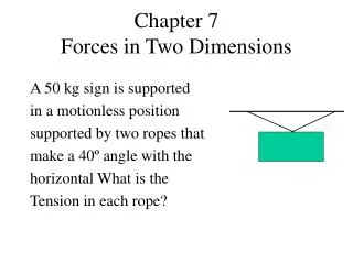
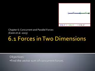
Forces in straight two-force members. The internal forces are equivalent to the axial force and the are reduced to a couple.

E N D
Forces in straight two-force members • Theinternalforces are equivalenttothe axial force and the are reducedto a couple.
Considering next a multiforce member AD (Fig. 7.20a), cutting it at J, and drawing the free-body diagram of portion JD, we conclude that the internal forces at J are equivalent to a force-couple system con- sisting of the axial force F, the shearing force V, and a couple M (Fig. 7.20b). The magnitude of the shearing force measures the shear at point J, and the moment of the couple is referred to as the bending moment at J. Since an equal and opposite force-couple system would have been obtained by considering the free-body diagram of portion AJ.
Shear and bending moment in a beam • To obtain the shear V and bending moment M at a given point C of a beam, we first determine the reactions at the supports by consider- ing the entire beam as a free body. We then cut the beam at C and use the free-body diagram of one of the two portions obtained in this fashion to determine V and M. In order to avoid any confusion regarding the sense of the shearing force V and couple M (which act in opposite directions on the two portions of the beam)
Once the values of the shear and bending moment have been determined at a few selected points of the beam, it is usually possible to draw a shear diagram and a bending-moment diagram representing, respectively, the shear and bending moment at any point of the beam
Relations among load, shear, and bending moment • The construction of the shear and bending-moment diagrams is facilitated if the following relations are taken into account. Denoting by w the distributed load per unit length (assumed positive if directed downward) • dV/dx=-w • dM/dx=V • VD –VC =-(area under load curve between C and D) • MD –MC=area under shear curve between C and D