Download
1 / 12
150 likes | 462 Views
GAS BURNERS. R 40 GS 20. To be connected when phase-phase. M. TB. N. Ph. 3. 2. 1. Manual Switch. 0’ sec. 1. 6. 10. 13. 4. 12. 2. 1. RMG 88.620A2. 2. 9. PA. P. 17. 7. 5. 1. 15. 16. Blue. Black. Capacitor. T2. T1. N. B4. S3. L1. TL. PG. TS. F. M. TB. N.

E N D
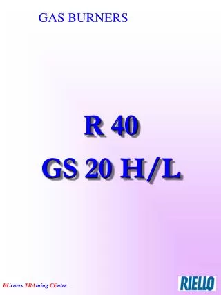
GAS BURNERS R 40 GS 20
To be connected when phase-phase M TB N Ph 3 2 1 Manual Switch 0’ sec 1 6 10 13 4 12 2 1 RMG 88.620A2 2 9 PA P 17 7 5 1 15 16 Blue Black Capacitor T2 T1 N B4 S3 L1 TL PG TS F
M TB N Ph 3 2 1 0’ sec 1 6 10 13 4 12 2 1 RMG 88.620A2 2 9 PA P 17 7 5 1 15 16 Blue Black Damper Motor Opens Capacitor T2 T1 N B4 S3 L1 Once Open Contact Will Change TL PG TS F
M TB N Ph 3 2 1 0’ sec 2 Tension At both # 9 and # 4 is the condition to begin the ignition cycle... …waiting time (2 sec)... 6 10 13 4 12 2 1 RMG 88.620A2 2 9 PA P 17 7 5 1 15 16 Blue Black Capacitor T2 T1 N B4 S3 L1 TL PG TS F
M TB N Ph 3 2 1 2’ sec 3 Fan Motor is Supplied Through #7 6 10 13 4 12 2 1 RMG 88.620A2 2 9 PA P 17 7 5 1 15 16 Air Pressure Switch Changes to Normally Opened Position (by 10 sec) Blue Black Capacitor T2 T1 N B4 S3 L1 TL PG TS F
M TB N Ph 3 2 1 2…40’ sec 4 6 10 13 4 12 2 1 RMG 88.620A2 2 9 PA P 17 7 5 1 15 16 Blue Black This Circuit Remains Until Prepurge is Completed (40 sec) Capacitor T2 T1 N B4 S3 L1 TL PG TS F
M TB N Ph 3 2 1 40’ sec 5 6 10 13 4 12 …then ignition: both # 13 and # 12 are energised 2 1 RMG 88.620A2 2 9 PA P 17 7 5 1 15 16 Blue Black Capacitor T2 T1 N B4 S3 L1 TL PG TS F
M TB N Ph 3 2 1 40..43’ sec 6 6 10 13 The Ignition Transformer is energised for 5 sec Flame Signal Max 3 sec 4 12 2 1 RMG 88.620A2 2 9 PA P 17 7 5 1 15 16 Blue Black Capacitor T2 T1 N B4 S3 L1 TL PG TS F
M TB N Ph 3 2 1 7 6 10 13 4 12 2 1 RMG 88.620A2 2 9 PA P 17 7 5 1 15 16 Blue Black Capacitor T2 T1 N B4 S3 L1 TL PG TS F
M TB N Ph 3 2 1 8 6 10 13 4 12 2 1 RMG 88.620A2 2 9 PA P 17 7 5 1 15 16 Blue Black Capacitor T2 T1 N B4 S3 L1 TL PG TS F
M TB N Ph 3 2 1 9 6 10 13 4 12 2 1 RMG 88.620A2 2 9 PA P 17 7 5 1 15 16 Blue Black Capacitor T2 T1 N B4 S3 L1 TL PG TS F
M TB N Ph 3 2 1 10 6 10 13 4 12 2 1 RMG 88.620A2 2 9 PA P 17 7 5 1 15 16 Blue Black Capacitor T2 T1 N B4 S3 L1 TL PG TS F