Download
1 / 4
40 likes | 173 Views
Fig. 1 above portrays an overall closed-loop architecture of autonomous relative navigation of a client satellite with an integrated sensor System composed of the SIGI (space Integrated GPS/INS), a star tracker for gyro updates, an imaging sensor to determine azimuth-elevation

E N D
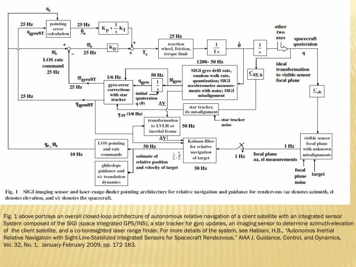
Fig. 1 above portrays an overall closed-loop architecture of autonomous relative navigation of a client satellite with an integrated sensor System composed of the SIGI (space Integrated GPS/INS), a star tracker for gyro updates, an imaging sensor to determine azimuth-elevation of the client satellite, and a co-boresighted laser range finder. For more details of the system, see Hablani, H.B., “Autonomos Inertial Relative Navigation with Sight-Line-Stabilized Integrated Sensors for Spacecraft Rendezvous,” AIAA J. Guidance, Control, and Dynamics, Vol. 32, No. 1, January-February 2009, pp. 172-183.
Fig. 7 illustrates the imaging of a client satellite with a sensor on a chaser satellite, yielding azimuth and elevation angle of the client satellite relative to the chaser satellite. For details, see Hablani, 2009, op cit. Fig. 5 portrays glide-slope guidance of the chaser satellite to approach a target satellite, aided with relative navigation. For Details, see Hablani, 2008, op cit., and Hablani, 2009, op cit.
Fig. 1 above depicts a single-axis closed-loop focal plane pointing and tracking system for relative navigation and guidance of a chaser satellite to get closer to a target satellite for rendezvous, inspection, or to repair it. For detailed functioning of this system, see Hablani, H.B., “Imaging Sensors Pointing and Tracking Controller Insensitive to Inertial Sensors Misalignments,” AIAA J. Guidance, Conrol, and Dynamics, Vol. 31, No. 4, July-August 2008, pp. 980-990.
The above figure shows that the line-of-sight command estimation error is essentially the same as the star tracker misalignment about the same axis. This biased command estimation error, however, does not cause bias in the focal plane image of the target, as shown in the figure below . For details, see Hablani, 2008, op cit. True and estimated inertial rate commands about the sensor focal plane y-axis: The rate commands change discretely with each firing of thrusters decreasing, in steps, relative velocity of the satellite to rendezvous.