Download
1 / 26
630 likes | 1.43k Views
EE3321 Electromagnetic Field Theory. Potential Energy, Energy Density Capacitance, Polarization Boundary Conditions. Potential Energy. The electric field and potential energy are directly related:

E N D
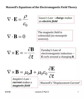
EE3321 Electromagnetic Field Theory Potential Energy, Energy Density Capacitance, Polarization Boundary Conditions
Potential Energy • The electric field and potential energy are directly related: • As a test charge +q moves in the direction that the field opposed it, its potential energy increases. • The electrostatic potential energy is the energy of an electrically charged particle (at rest) in an electric field. • The energy difference between two potentials is given by U = q(V2 – Vref) Joules (VAs)
Example Potential Energy U = +qV Charge Q R V(∞→R) =Vref = 0 Test Charge +q Potential V = kQ R
Observations • The potential at infinity is zero • A positive test charge +q gains potential as it gets closer to the charge +Q • A negative test charge –q loses potential as it gets closer to the charge +Q.
Cathode Ray Tube • The CRT is a vacuum tube containing an electron gun (a source of electrons) and a fluorescent screen used to create images in the form of light emitted from the fluorescent screen. • The image may represent electrical waveforms (oscilloscope), pictures (television, computer monitor), radar targets and others.
CRT Simplified Set Up • Once the electrons leave the cathode, they accelerate toward the grid. • Electrons entering the deflecting plate region and change directions depending on the voltage between the plates.
Exercise • An electron moves at a constant velocity v = voax. Assume that the electron enters in a field E = - 1 a z(V/m) at x =0. • Compute the potential energy U the electron loses as it moves from A (at z = 0 cm) to B (at z = 0.5 cm). Recall e = 1.602 x 10 – 19 As.
Energy Stored in an E Field • Using Gauss’ Law in differential form and the Divergence theorem and it can be shown that the energy density or energy per unit volume (J/m3) of the electric field is: u = ½ є |E|2 (Joules/m3) • The total energy stored in the electrostatic field is U = ∭ u dV (Joules) where dV is the volume differential.
Example • Let E = 9 V/mm in between the plates. Suppose that the area A = 1 cm2 and the dielectric thickness is d = 1 mm. Find the energy stored by the capacitor for a relative permittivity of 2.8. Neglect (field) fringing effects. • Notice that the field is constant • Calculate the energy density • Calculate the volume between the capacitor plates
Exercise • Calculate the energy stored in the field produced by a metal sphere of radius a holding a charge Q. • Determine the electric field E • Find the energy density u • Set up the integral for U • Integrate over space a<R< ∞
Capacitance • As shown above a capacitor consists of two conductors separated by a non-conductive region. • The non-conductive substance is called the dielectric medium. • The conductors contain equal and opposite charges on their facing surfaces, and the dielectric contains an electric field. • A capacitor is assumed to be self-contained and isolated, with no net electric charge and no influence from an external electric field.
Capacitance • An ideal capacitor is wholly characterized by its capacitance C (in Farads), defined as the ratio of charge ±Q on each conductor to the voltage V between them C = Q/V • More generally, the capacitance is defined in terms of incremental changes C = dq/dv
Parallel Plate Capacitor • From Gauss’ Law the charge and the electric field between the plates is related by • Likewise, the line integral relating the potential and the electric field simplifies to • Thus the capacitance is given by
Exercise • Consider a parallel plate capacitor. Derive an expression for the stored energy U in terms of the capacitance C and the potential V.
Polarization • Suppose that a capacitor is charged up by connecting it to a voltage source V which is then removed. • A fixed charge Q is placed on its upper plate and –Q on the lower plate. • Suppose the capacitor is air filled. In this case, • The capacitance is
Polarization • Next assume that the capacitor is filled with dielectric material as illustrated here. • Since the charge does not change, the electric flux D is the same as before. • However, the electric field E changes to
Polarization • The decrease of E is said to be due to the polarization P of the dielectric molecules which opposes E: • But the capacitance increases to
Exercise • The relative permittivity of air is 1.0 and that of quartz is about 4.5. Calculate the difference in capacitance for two capacitors with identical geometry using these two dielectric materials.
Electric Boundary Conditions • On a perfect conductor • The component of E parallel to the conducting surface is zero • The component of D normal to the conducting surface is numerically equal to the charge density • On a perfect dielectric material • The component of E parallel to the interface is continuous • The component of D normal to the interface is continuous
Perfect Dielectric Medium • Tangential components of E are continuous E1t = E2t Medium 1 (air) Medium 2 WATER DROPPLET
Perfect Dielectric Medium • Normal components of E are discontinuous ε1E1n = ε2E2n Medium 1 (air) no free charges Medium 2 WATER DROPPLET
Perfect Conductor Medium • Tangential components of E are zero E1t = E2t = 0 Medium 1 (air) X Short circuit Medium 2 WATER DROPPLET
Perfect Conductor Medium • Normal components of E are discontinuous E1n≠ 0 E2n= 0 Medium 1 (air) Medium 2 WATER DROPPLET
Exercise • Consider a dielectric interface at z = constant. • Let єr1 = 2, єr2 = 5, and E1 = 2ax + 3ay + 5az • Find E2 єr1 = 2 єr2 = 5
Homework • Read textbook sections 4-8, 4-9, 4-10, 4-11 • Solve problems 4.43, 4.45, 4.50, 4.51, 4.52, 4.54