Download
1 / 34
360 likes | 528 Views
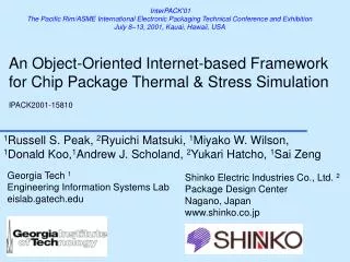
InterPACK'01 The Pacific Rim/ASME International Electronic Packaging Technical Conference and Exhibition July 8–13, 2001, Kauai, Hawaii, USA. An Object-Oriented Internet-based Framework for Chip Package Thermal & Stress Simulation IPACK2001-15810.

E N D
InterPACK'01 The Pacific Rim/ASME International Electronic Packaging Technical Conference and Exhibition July 8–13, 2001, Kauai, Hawaii, USA An Object-Oriented Internet-based Framework for Chip Package Thermal & Stress SimulationIPACK2001-15810 1Russell S. Peak, 2Ryuichi Matsuki, 1Miyako W. Wilson, 1Donald Koo,1Andrew J. Scholand, 2Yukari Hatcho, 1Sai Zeng Shinko Electric Industries Co., Ltd. 2 Package Design Center Nagano, Japan www.shinko.co.jp Georgia Tech 1 Engineering Information Systems Lab eislab.gatech.edu
Chip Package Products Shinko Quad Flat Packs (QFPs) Plastic Ball Grid Array (PBGA) Packages
Traditional VTMB FEA Model CreationManually Intensive: 6-12 hours VTMB = variable topology multi-body FEA Model Planning Sketches - EBGA 600 Chip Package
Outline • Analysis Integration Background • CAD-CAE Interoperability Research & Development • Chip Package Analysis Tool Overview • On Automating Variable Topology Multi-Body (VTMB) FEA Problems • Summary
X-Analysis Integration TechniquesX = Design, Mfg., Sustainment, … a. Multi-Representation Architecture (MRA) b. Explicit Design-Analysis Associativity c. Analysis Module Creation Methodology
An Introduction to X-Analysis Integration (XAI)Short Course Outline Part 1: Constrained Objects (COBs) Primer • Nomenclature Part 2: Multi-Representation Architecture (MRA) Primer • Analysis Integration Challenges • Overview of COB-based XAI Part 3: Example Applications • Airframe Structural Analysis (Boeing) • Circuit Board Thermomechanical Analysis (DoD: ProAM; JPL/NASA) • Chip Package Thermal Analysis (Shinko) • Summary Part 4: Advanced Topics & Current Research
Outline • Analysis Integration Background • CAD-CAE Interoperability Research & Development • Chip Package Analysis Tool Overview • On Automating Variable Topology Multi-Body (VTMB) FEA Problems • Summary
Tool Usage Overview Preliminary Design Analysis Module Setup & Usage 1 2b Automated FEA Meshing & Solution 3a 3b Thermal Results Documentation Assistance 2a
Flexible High Diversity Design-Analysis Integration Electronic Packaging Examples: Chip Packages/Mounting Shinko Electric Project: Phase 1 (completed 9/00) Design Tools Modular, Reusable Template Libraries Analysis Modules (CBAMs) of Diverse Behavior & Fidelity Prelim/APM Design Tool Analysis Tools XaiTools ChipPackage XaiTools ChipPackage General Math Mathematica FEAAnsys Thermal Resistance Analyzable Product Model 3D XaiTools PWB DB Materials DB* ThermalStress EBGA, PBGA, QFP Basic 3D** Basic Documentation Automation AuthoringMS Excel ** = Demonstration module
Using Internet/Intranet-based Analysis SolversThick Client Architecture Self-Serve Engineering Service Bureau (ESB) Users Client PCs Server Machines June’99-Present: EIS Lab - Regular internal use U-Engineer.com - Demo usage: - US - Japan Nov.’00-Present: Electronics Co. - Began production usage (dept. Intranet) Future: Company Intranet and/or U-Engineer.com (commercial) - Other solvers Thick Client CORBA Daemon Iona orbixdj XaiTools CORBA IIOP CORBA Servers Internet XaiTools Ansys Solver Server XaiTools Ansys Solver Server XaiTools Math. Solver Server XaiTools Ansys Solver Server FEA Solvers Ansys Internet/Intranet ... Math Solvers Mathematica
APM Design ToolPreliminary Design of Packages - PBGA Screens APM = analyzable product model
Example Chip Package Idealizations (PBGA) Idealization for solder-joint/thermal ball Idealization for thermal via Courtesy of Shinko - see [Koo, 2000]
COB-based Analysis TemplateTypical Input Objects for EBGA Thermal Resistance Module COB = constrained object Customized Analysis Module Tool with idealized package cross-section Generic COB Browser with design and analysis objects (attributes and relations)
COB-based Analysis TemplateTypical Highly Automated Results COB = constrained object Analysis Module Tool Auto-Created FEA Inputs (for Mesh Model) FEA Temperature Distribution Thermal Resistance vs. Air Flow Velocity
Test Cases - ShinkoAuto-Generated FEA Mesh Model of PBGA 256 with Thermal Vias FEA mesh model with strong inter-body coupling 29 idealized bodies 10 idealized materials 1 main pattern ~3 sub patterns Small Idealized Vias Thin Copper Layers
Results Validation Thermal resistance (a) (b) (c) Good comparisons: (a) simulation via VTMB algorithm (in XCP) (b) simulation via traditional manual approach (c) physical measurements
Outline • Analysis Integration Background • CAD-CAE Interoperability Research & Development • Chip Package Analysis Tool Overview • On Automating Variable Topology Multi-Body (VTMB) FEA Problems • Summary
Traditional VTMB FEA Model CreationManually Intensive: 6-12 hours VTMB = variable topology multi-body FEA Model Planning Sketches - EBGA 600 Chip Package
Variable Topology Multi-Body (VTMB) FEA Meshing Challenges Idealized Analytical Bodies Decomposed FEA Geometry Models Design Model Meshing & Solving 1a 1b 1 2 2 1c 3a 3b 3c 3 original Labor-intensive “chopping” 1a 1b 1c 1 2 2 1d 1e 3 3a 3b topology change (no body change) 1a 1b 1 2 2 1c 3 3 1d 4 4a 4b 4c body change (includes topology change)
Product Information-Driven FEA MethodologyPurpose of VTMB Methodology thermal stress CBAMs PWB APMs Chip package APMs thermal resistance CBAMs ANSYS SMMs VTMB Methodology VTMB FEA Models create algorithmij once algorithmij use algorithmij many times Design Instances Analysis Instances Design Types i = 1…m Analysis Typesj = 1…n for a given ij j{1…n} (not all design types have all analysis types) e.g.) for i=1(EBGA), j=1(thermal resistance) j=2 (thermal stress) for i=2 (PWB), j=1 (warpage) VTMB= variable topology multi-body
MethodologyScope of VTMB algorithmij for cbamij G idealizations, transformations, Y allowables VTMB algorithmij for cbamij [Koo, 2000] Analysis Subsystems [Tamburini, 1999] Part Feature & Assembly Structure Pseudo-Analysis Building Blocks Context-Based Analyzable Product Model (pseudo-ABBs) Analysis Model Step 2 (CBAM) Step 1a [Peak, 2001] Boundary Condition Objects & Discipline Step 1b Solution Method Models Conditions & boundary variables (SMMs) Analysis Next-Higher Context CBAMs Step 3 Behavior/Mode Associativity Objectives F Linkages, allowable Step 4 MoS actual
Design Changes with Large Topology Impact Example Variations: PBGAs & EBGAs EBGA 600 with 2 Steps PBGA 313 with Thermal Vias & Thermal Balls EBGA 325 with No Steps 2D partial views of 3D models
Design Change with Small Topology ImpactHeat Spreader Size Variations - EBGA 600 Idealized Analytical Models thin & large thick & small FEA Mesh Models z-direction topology changes 2D partial views of 3D models
Test Cases - ShinkoAuto-Generated FEA Model: QFP PCDPH FEA mesh model with strong inter-body coupling 23 idealized bodies 9 idealized materials 1 main pattern ~3 sub patterns
Design Changes with Large Topology Impact Example Variations: QFPs QFP 208 DPH HS/Tape QFP 128 SL Die Pad 2D partial views of 3D models
Basic Stress Analysis Module ToolHighly automated FEA model creation PBGA 625 • Re: thermal model: • Same APM (but different idealizations) • CORBA-based • solvers, etc. • Pattern-based • meshing • Adjustable mesh density
Multi-Fidelity IdealizationsMode-dependent Idealized Geometries; Same Dimension Thermal Resistance Idealized Geometry (3D) FEA Model Common Design Model Thermal Stress Idealized Geometry (3D) FEA Model
Outline • Analysis Integration Background • CAD-CAE Interoperability Research & Development • Chip Package Analysis Tool Overview • On Automating Variable Topology Multi-Body (VTMB) FEA Problems • Summary
Pilot & Initial Production Usage ResultsProduct Model-Driven Analysis VTMB = variable topology multi-body technique [Koo, 2000] • Reduced FEA modeling time > 10:1 (days/hours minutes) • Reduced simulation cycle > 75% References [1] Shinko 5/00 (in Koo, 2000) [2] Shinko evaluation 10/12/00 • Enables greater analysis intensity Better designs • Leverages XAI / CAD-CAE interoperability techniques • Objects, Internet/web services, ubiquitization methodology, …
Summary of Tools and Servicesoffered via Georgia Tech Research Corp.http://eislab.gatech.edu/ • XaiTools FrameWork™ • General-purpose analysis integration toolkit • Product-Specific Toolkits • XaiTools PWA-B™ • XaiTools ChipPackage™ • U-Engineer.com™ • Internet-based engineering service bureau (ESB) • Self-serve automated analysis modules « Full-serve consulting • Research, Development, and Consulting • Analysis integration & optimization – Short courses • Product-specific analysis module catalogs • Internet/Intranet-based ESB development • Knowledge-based engineering & information technology • PDM, STEP, GenCAM, XML, UML, Java, CORBA, Internet, … • CAD/CAE/CAM, parametric FEA, thermal & mechanical analysis
For Further Information ... • EIS Lab web site: http://eislab.gatech.edu/ • Publications, project overviews, tools, etc. • See: Publications DAI/XAI Suggested Starting PointsX-Analysis Integration (XAI) Technologyhttp://eislab.gatech.edu/pubs/reports/EL002/ • XaiTools™ home page: http://eislab.gatech.edu/tools/XaiTools/ • Pilot commercial ESB: http://www.u-engineer.com/ • Internet-based self-serve analysis • Analysis module catalog for electronic packaging • Highly automated front-ends to general FEA & math tools