Download
1 / 26
260 likes | 396 Views
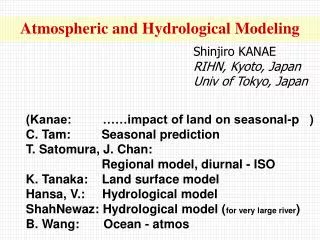
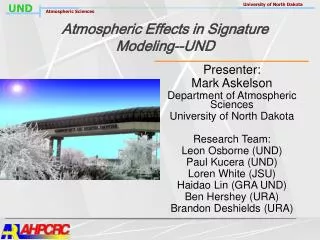
Atmospheric Effects in Signature Modeling--UND. Presenter: Mark Askelson Department of Atmospheric Sciences University of North Dakota Research Team: Leon Osborne (UND) Paul Kucera (UND) Loren White (JSU) Haidao Lin (GRA UND) Ben Hershey (URA) Brandon Deshields (URA). Army Issues.

E N D
Atmospheric Effects in Signature Modeling--UND Presenter: Mark Askelson Department of Atmospheric Sciences University of North Dakota Research Team: Leon Osborne (UND) Paul Kucera (UND) Loren White (JSU) Haidao Lin (GRA UND) Ben Hershey (URA) Brandon Deshields (URA)
Army Issues • Electromagnetic Propagation • Significant Atmospheric Effects • Important bands • Visible • Infrared Superior image owing to superrefraction. Sandstorms in Iraq, from Associated Press. Image from Iran-Iraq War.
Army Issues • Consequences • Soldier and systems performance • Target identification • Important Parameters • Aerosols • Smoke/dust • Refractive index variations • Turbulence (Cn2) • Absolute humidity (IR extinction) • Focus is boundary layer Image Distortion in the Far IR (8-12 um FLIR) over a 2 km path for Cn2 = 10-12 m-2/3, courtesy of Jon Mercurio.
Army Issues • Acoustic Propagation • Reasons • Enemy detection (e.g., sniper) • Detection avoidance • Significant atmospheric effects
Army Issues • Atmospheric EM and Acoustic Effects • Need information concerning large-scale (relatively easy) and small-scale (hard) atmospheric structures • Atmospheric Analysis Systems • Two components • Predictive • Observations • Typically geared towards larger scale phenomena (> 10 km).
Army Issues • Need to develop to resolve smaller scale phenomena, especially in boundary layer • LAPS • Developed by NOAA Forecast Systems Laboratory (FSL) • Local Analysis and Prediction System • Base weather analysis system software package
Army Issues • Research Areas • Response Filter (Askelson & Lin) • Improve handling of irregularly spaced data in LAPS → better analysis fields. • LAPS Boundary Layer (Osborne) • Modify LAPS to support broader boundary layer physics with emphasis on moisture and mass field enhancement; enhance boundary layer analysis detail. • EM Effects (Kucera) • Diagnose important atmospheric fields, develop EM ray tracing algorithms, and study propagation effects.
Askelson & Lin: Response Filter • Response Filter • Response function • Amplitude and phase modulations of analysis scheme. • Filter efficacy • Determined by two factors • Weight function shape • Distribution of observations • Analysis systems oftentimes ignore distribution of observations, which is critically important.
Askelson & Lin: Response Filter • Example • Coherent input field looks incoherent after analysis (upper right) owing to impact of irregular data distribution the response function. • Want to improve technique so that result is coherent (lower right)
Askelson & Lin: Response Filter • Design • Linear least squares problem • Find weights that produce desired response function • Take derivative with respect to weights • Invert matrix for weights
Askelson & Lin: 1D Results Barnes scheme Response filter
Askelson & Lin: 2D Results • Early test results • Simple schemes expected to perform well. • Input field (upper-left), perfect analysis field (bottom-left), Barnes scheme (upper-right), response filter (lower-right). • Response filter phase shift, but ripples. • Designing tougher test…response filter should be far superior.
Askelson & Lin: Conclusions • Accomplishments • Designed, implemented, and tested1D response filter • 2D response filter • Developed and implemented • Testing still under way • 3D • Designed • Future work • Complete work with 3D filter and complete integration of filters into LAPS
Osborne: Core Analysis Method J = JB +JO +JC • JB is a weighted fit of the analysis to the background field • JO is a weighted fit of the analysis to the observations • JC is a term which can be used to minimize the noise produced by the analysis (e.g., by introducing a balance). 3D-Variational adjustment is applied to objectively analyzed fields containing heterogeneous data types:
Osborne: Three-Dimensional Variational Assimilation • Domain initialized with a previous forecast for mass, momentum and moisture • Utilizes data models i.e. forward radiance for GOES satellite radiances • Adjustments are made throughout the atmosphere including new data layers in the PBL Transformation matrix, K, is replaced by models for various remotely observed data
Osborne: Domain Specifications • Vertical Levels: • Boundary layer (Surface to 700 hPa) • From 20-25 levels (depends upon actual surface pressure) • Free atmosphere (700 hPa to 100 hPa) • 14 levels • Horizontal Grid Spacing: • 5 kilometers • X-Y grid points vary from 125 x 125 to 265 x 265 depending upon domain considered • Domains presently exist for • Mid-Atlantic (Washington, D.C.) • Southeast US (Atlanta) • South Plains (Oklahoma City)
Osborne: Accomplishments Modification of LAPS code to support non-uniform vertical levels Expansion of LAPS levels within atmospheric boundary layer Incorporated GOES radiance data and GPS integrated precipitable water Early validation shows a significant improvement in boundary layer dewpoint temperature analyses (figure below .. positive values denote improvements) Vertical variation of the 282 K surface across the Mid-Atlantic analysis domain
Osborne: Future Work Incorporation of additional quality controls to account for cloudy conditions. Testing of methodology using the Askelson Filter Further testing of schemes at finer horizontal resolutions Software documentation and report preparation
Kucera: EM Effects • Objectives: • Develop algorithms to calculate refractivity fields from LAPS output fields • Evaluate LAPS-derived refractivity fields • Expand 2D ray tracing model to incorporate horizontal refractivity gradients (current model assumes a spherically stratified atmosphere i.e. no horizontal gradients) • Study effects of varying atmospheric conditions on electromagnetic wave propagation • Issues • Refraction has strong dependence on pressure, temperature, and moisture variations in the atmosphere • Ray tracing code currently uses single sounding to calculate the vertical profile of refractivity and assumes a homogenous atmosphere • Refractivity will have strong gradients around mesoscale features such as thunderstorms, sea breezes, ocean-land boundaries, which are not captured by observations (need predictive component of analysis system) • Electromagnetic wave propagation is greatly affected by these strong gradients
Kucera: N Computed from LAPS • Computation of Refractivity from LAPS • Part of Summer Institute project • Computation • Kucera, Askelson, & Hershey • Visualization • Kucera, Askelson, & Deshields Vis5d visualization of refractivity computed from LAPS analysis output at 915 mb over the southern plains.
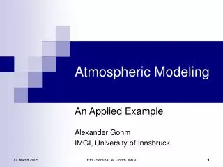
Kucera: Atmospheric Effects on EM Propagation • Case Study – Refractivity/Beam Propagation over Guam • Combines a beam propagation model with a Digital Elevation Model (DEM) Guam DEM maps. Maximum elevation is 450 m above sea level
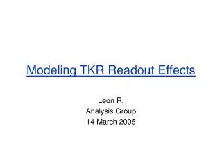
Kucera: Atmospheric Effects on EM Propagation The red plane show the location of the 0.0° elevation beam assuming constant refractivity profile in all directions.
Kucera: Atmospheric Effects on EM Propagation The red plane show the location of the 0.0° elevation beam assuming constant refractivity profile in all directions.
Kucera: Conclusions • Accomplishments • Developed infrastructure for computing 3D refractivity fields from LAPS analyses. • Visualization (ingested into Vis5d). • Studied atmospheric effects on EM propagation. • Future work • Evaluate LAPS derived fields. • Expand 2D ray tracing code to handle horizontal refractivity gradients. • Thorington.
Conclusions • Army relevance and needs • Atmospheric fields affect EM and acoustic signals, which impact soldier and system performance in the battlefield. • Needs: Improved analysis systems and computational infrastructures to diagnose (& predict) effects. • HPC • Propagation calculations.
Conclusions • Collaborations • Doug Brown • ARL BED • Charles Thorington • NetASPx • Propagation calculations • Robert Dumais • ARL BED (WSMR) • Use of response filter in their analysis system