Download
1 / 28
280 likes | 384 Views
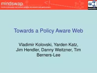
A policy-aware switching layer for data centers. ACM Special Interest Group on Data Communication (SIGCOMM’08). Authors: Dilip A. Joseph, Arsalan Tavakoli , Ion Stoica University of California, Berkeley, CA, USA Speaker: Ming Chao, Hsu National Cheng Kung University. Preface.

E N D
A policy-aware switching layer for data centers ACM Special Interest Group on Data Communication (SIGCOMM’08) • Authors: Dilip A. Joseph, ArsalanTavakoli, Ion Stoica • University of California, Berkeley, CA, USA • Speaker: Ming Chao, Hsu • National Cheng Kung University
Preface • ACM Association for Computing Machinery • SIGCOMM ACM Special Interest Group on Data Communication
Preface • Ion Stoica • Research • My area of research is distributed systems, and networking with an emphasis on Quality of Service (QoS) and resource management. I am equally interested in designing algorithms and systems with strong theoretical foundations, and in providing practical implementations that are deployable in the real world. Some of the projects I am/was involved are below: • Distributed Systems and Cloud Computing • Mesos: A Platform for Fine-Grained Resource Sharing in the Data Center • Spark: Cluster Computing with Working Sets • Peer-to-Peer and Overlay Networks • OCALA: Overlay Convergenge Architecture for Legacy Applications • Internet Indirection Infrastructure (i3) • OML: Overlay MAC Layer • Chord • Scalable Network Services (The Denali Project) • Self-Verifyable Protocols • QoS and Resource Management based with Dynamic Packet State (DPS) • Core-Stateless Fair Queueing (CSFQ) • Guaranteed Services with no Per-Flow State • REUNITE: A Recursive Unicast Approach to Multicast • Hierarchical Fair Service Curve (HFSC)
Preface • Dr. Dilip Antony Joseph I currently work for a technology start-up in the San Francisco Bay Area. • I graduated with a PhD in Computer Science from the University of California Berkeley (UCB). I did my undergraduate studies at IIT Madras, India, from where I received a Bachelor of Technology degree in Computer Science. Most of my schooling was at Bhavan'sVidyaMandir, Girinagar in India, though I spent my early school years in Kuwait.
Outline • INTRODUCTION • BACKGROUND • Data Center Network Architecture • Limitations of Current Middlebox Deployment Mechanisms • DESIGN OVERVIEW • MINIMAL INFRASTRUCTURE CHANGES • Forwarding Infrastructure • Unmodified Middleboxes and Servers • NON-TRANSPARENT MIDDLEBOXES • Policy Specification • Middlebox Instance Selection • IMPLEMENTATION AND EVALUATION • LIMITATIONS • RELATED WORK
INTRODUCTION • Data centers typically host tens or even thousands of different applications, To protect, manage and improve the performance of these applications, data centers deploy a large variety of middleboxes • firewalls, load balancers, SSLoffloader, web caches, and intrusion prevention boxes. • To ensure that traffic traverses the desired sequence of middleboxes, administrators must rely on overloading existing path selection mechanisms • such as layer-2 spanning tree construction
INTRODUCTION • It is harder to rely onthe current ad-hoc mechanism to ensure the following highly desirable properties: • (i) Correctness: • Traffic should traverse middleboxes in the sequence specified by the network administrator under all network conditions. • (ii) Flexibility: • The sequences of middleboxes should be easily (re)configured as application requirements change. • (iii) Efficiency: • Traffic should not traverse unnecessary middleboxes.
INTRODUCTION • Policy-aware switching layer (or PLayer) • A proposal that aims to address the limitations of today's data center middlebox deployments • Policy-aware switches, or pswitches • Maintain the middlebox traversal requirements of all applications in the form of policy specifications. • Classify incoming traffic and explicitly redirect them to appropriate middleboxes • guaranteeing middlebox traversal in the policy-mandated sequence.
BACKGROUND • Data Center Network Architecture: • Scale: • The network may consist of tens of thousands of machines running thousands of applications and services. • Middlebox-based Policies: • The traffic needs to traverse various middleboxes, such as firewalls, intrusion prevention boxes, and load balancers before being delivered to applications and services. • Low-Latency Links: • The network is composed of low latency links which facilitate rapid information dissemination • Allow for indirection-mechanisms with minimal performance overhead.
BACKGROUND • The physical network topology in a data center is typically organized as a three layer hierarchy • The access layer provides physical connectivity to the servers in the data centers • The aggregation layer connects together access layer switches. • Middleboxes are usually deployed at the aggregation layer to ensure that traffic traverses middleboxes before reaching data center applications and services. • Multiple redundant links connect together pairs of switches at all layers, enabling high availability at the risk of forwarding loops.
BACKGROUND Prevalent 3-layer data center network topology.
BACKGROUND • Suppose we want traffic between servers S1 and S2 always traverse a firewall • There are three ways to achieve this: • (i) Use the existing aggregation layer firewalls • (ii) Deploy new standalone firewalls • (iii) Incorporate firewall functionality into the switches themselves
BACKGROUND • The first option of using the existing aggregation layer firewalls requires all traffic between S1 and S2 to traverse the path (S1, A1, G1, L1, F1, G3, G4, F2, L2, G2, A2, S2) • Problem: • it wastes resources by causing frames to gratuitously traverse two firewalls instead of one, and two load balancers.
BACKGROUND • Remove physical connectivity: • spanning tree protocol in forwarding loops. • lose the fault tolerance property of the original topology • Manipulate link costs: • Use the spanning tree construction algorithm to avoid these links • redundant network policy, fault-tolerance and traffic engineering requirements • Separate VLANs: • Placing S1 and S2 on separate VLANs • it disallows applications, clustering protocols and virtual server mobility mechanisms • It also forces all applications on a server to traverse the same middlebox sequence
DESIGN OVERVIEW • A policy is of the form: [Start Location, Traffic Selector]->Sequence. • frames with 5-tuples (source and destination IP addresses and port numbers, and protocol type) • Policies are automatically translated by the PLayer into rules that are stored at pswitches in rule tables. • A rule is of the form [Previous Hop, Traffic Selector] : Next Hop. • Each rule determines the middlebox or server to which traffic of a particular type, arriving from the specified previous hop, should be forwarded next.
DESIGN OVERVIEW • The pswitch identifies frames arriving from the core router and the load balancer based on their source MAC addresses (R and L, respectively). • The pswitch determines the next hop for the frame by matching its previous hop information and 5-tuple against the rules in the rule table.
DESIGN OVERVIEW • Multiple equivalent instances of middleboxes are often deployed for scalability and fault tolerance. • The first rule in the table species that incoming frames can be sent either to firewall F1 or to firewall F2.
DESIGN OVERVIEW • How thePLayer supports different policies for different applications and how forwarding load is spread across multiple pswitches.
NON-TRANSPARENT MIDDLEBOXES • Policy Specification • Policies for different segments of the logical middlebox sequence traversed by traffic between A and B.
MINIMAL INFRASTRUCTURE CHANGES • Pswitch Design & Standard Forwarding • Each physical interface is shown as two separate logical interfaces • an input interface and an output interface. • A pswitch consists of two independent parts • the Switch Core and the Policy Core
MINIMAL INFRASTRUCTURE CHANGES • Switch Core : The Switch Core provides regular Ethernet switch functionality • forwards Ethernet frames based on their destination MAC addresses • performs MAC address learning • participates in the Spanning Tree Protocol to construct a loop-free forwarding topology. • Policy Core : The Policy Core redirects frames to the middleboxes dictated by policy. • Only frames containing IP packets are considered. • Non-IP frames like ARP requests are forwarded by the Switch Core as in regular Ethernet switches. • The RuleTable • stores the rules used for matching and forwarding frames • The FailDetect module • a pswitch interface monitors the liveness of the connected middleboxand reports to the middlebox controller • e.g., ICMP pings, layer-7 content snooping, SNMP polling, TCP health checks
IMPLEMENTATION AND EVALUATION • Implementation • Pswitches in software using Click • An unmodified Click Etherswitch element formed the Switch Core, • The Policy Core was implemented in 5500 lines of C++ • Commercial quality software middleboxes running on standard Linux PCs • (i) Netfilter/iptables based firewall, (ii) Bro intrusion detection system, and (iii) BalanceNG load balancer. • Net-SNMP package for implementing SNMP-based middleboxliveness monitoring
IMPLEMENTATION AND EVALUATION • Topology A->B: Logical topology A represents our starting point and the most basic topology • Topology B->C: Adding a second firewall, Firewall 2, in parallel with Firewall 1, in order to split the processing load resulted in logical topology C.
IMPLEMENTATION AND EVALUATION • Topology C->D: We next inserted a load balancer in between the firewalls and web server 1, and added a second web server, yielding logical topology D.
IMPLEMENTATION AND EVALUATION • Topology D->E: In order to demonstrate the PLayer ‘s flexibility, we flipped the order of the firewalls and the load balancer in logical topology D, yielding topology E.
IMPLEMENTATION AND EVALUATION • Topology E->F: To further demonstrate the PLayer's flexibility, we updated the policies to implement logical topology F
IMPLEMENTATION AND EVALUATION • Benchmarks • hardware switchprototype pswitches on the NetFPGA boards. • Nuttcp and ping for measuring TCP throughput and latency. • (a)The pswitchv.s. standalone ClickEtherswitch, at throughputs of 750 Mbps and 912 Mbps,incurring latencies of 0.3 ms and 0.25 ms. • (b)The on-path firewall deployment achieved an end-to-end throughput of 932 Mbps and a latency of 0.3 ms, while the pswitch based firewall deployment achieved 350 Mbps with a latencyof 0.6 ms. • A pswitch takes between 1300 and 7000 CPU ticks (1 tick = 1/3000 microsecond on a 3GHz CPU) to process a frame. • A frame entering a pswitch input interface from a middlebox or server is processed and emitted out of the appropriate pswitch output interfaces in 6997 CPU ticks. • Approximately 50% of the time is spent in rule lookup (from a 25 policy database) and middlebox instance selection, and 44% on frame encapsulation. • An encapsulated frame reaching the pswitch directly attached to its destination server/middlebox was decapsulated and emitted out to the server/middlebox in 1312 CPU ticks
RELATED WORK • MPLS traffic engineering • To modified and relay MPLS labels • Multi-hop network architecture • Per-flow multi-hop address resolution to determine the middleboxes • Policy Based Routing • Different routing and tunneling mechanisms. • The Internet Indirection Infrastructure and Delegation Oriented Architecture