Download
1 / 26
270 likes | 756 Views
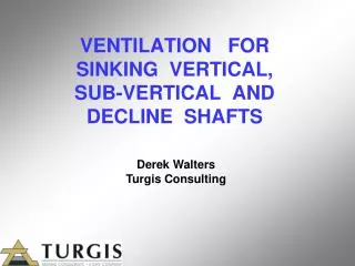
VENTILATION FOR SINKING VERTICAL, SUB-VERTICAL AND DECLINE SHAFTS. Derek Walters Turgis Consulting. Virtually every shaft or decline sunk is unique in some way. Major differences being:. Location Size and Depth Capacity Infrastructure

E N D
VENTILATION FOR SINKING VERTICAL,SUB-VERTICAL AND DECLINE SHAFTS Derek Walters Turgis Consulting
Major differences being: • Location • Size and Depth • Capacity • Infrastructure • Amount of development required from shaft or decline
Regulatory requirements • No longer prescribed (formerly 0.15 m³/s/m² face area). • Based on risk assessment and occupational exposure limits.
Occupational Exposure Limits (OEL) • OEL = Time weighted average 8 hour day 40 hours a week. • OEL – C = Instantaneous value which must never be exceeded. • OEL-STEL = Maximum exposure for 15 minute TWA and not more than 4 times per day.
Operating outside South Africa: • Comply with local regulations. Or • In the absence of local regulations use South African regulations. • These comply with internationally accepted norms and are thus defensible.
The purpose of ventilation is to dilute and remove pollutants. • Always assume that flammable gas may occur. • SA Limit 1.4 % flammable gas in atmosphere. • Define “Atmosphere” as 150 mm away from the source in any direction. • Design must be robust enough to cater for abnormal but reasonably anticipated events.
Vertical shafts Determine requirement for ventilating the shaft barrel. Determine work that is to be done concurrently or in conjunction with sinking. • Including: • Station and other development • Raise Boring • Holing with other excavations
Determining basic air requirements Ordinary sinking: Air volume providing minimum of 0.5 m/s in shaft is good practice. Example: An 8.0 m shaft would require 50.3 m² x 0.5 = 25.2 m³/s
Determining re-entry times • Shaft diameter: 8 m diameter (50.3 m²) • Required re-entry time: 15 minutes • Number of air changes: 8 between face & stage • Distance from the face to the stage when raised for blasting: 50 m • Air quantity (Q) = (Air changes x Volume) / Time • Q = ( 8 x 50.3 x 50) / 15 x 60 = 22.3 m³/s • In this case the minimum air quantity required is 22.3 m³/s
Ventilation of development from the shaft • Unique design for each shaft. • Designed as an integral part of the sinking shaft
Common problems • Inadequate air for development activities. • Column leakage due to improper installation and damage.
Recommended 2 or 3 mm thick “Corten” columns They are: • Robust • Can easily be refurbished and re-used
Decline development Single decline using conventional force system with flexible ducting (world norm). Twin declines.
Determining air requirements • Currently no legislated minimum air quantity in SA • Many other countries have regulations in place. • These minimum air quantities vary considerably from country to country. • Suggested volume is 0.075m³/s/kW rated power • A 150 kW LHD would require (150 x 0.075) = 11.3 m³/s
Sizing of ventilation columns Identical 1.0 m Ø columns, 1500 m long, 15% leakage.
Heat loads These are site specific and are affected by: • Ambient conditions • Depth • Rock geothermal gradient • Rock thermal characteristics • Area of rock exposed • Diesel equipment • Other mechanical and electrical heat loads • Ground water inflow rate
To determine the need for cooling a heat balance must be done. There are a number of computer programs to calculate this and to predict The working conditions in the decline being sunk.
Conclusions The ventilation system should be uniquely designed to cater for sinking and any additional development that may be required. Avoid the “one size fits all” approach.