Download
1 / 30
330 likes | 524 Views
Display Systems. Viewing Images. In This Section. We will explore how display systems work. Cathode Ray Tube Television Computer Monitor Flat Panel Display Liquid Crystal Display. Cathode Ray Tube. A common device used in televisions, and computer monitors.

E N D
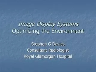
Display Systems Viewing Images
In This Section... • We will explore how display systems work. • Cathode Ray Tube • Television • Computer Monitor • Flat Panel Display • Liquid Crystal Display Chester F. Carlson Center for Imaging Science
Cathode Ray Tube • A common device used in televisions, and computer monitors. • The tube directs electrons to form an image on a screen. Chester F. Carlson Center for Imaging Science
Cathode Ray Tube A cathode ray tube (CRT) is a special kind of vacuum tube. Chester F. Carlson Center for Imaging Science
Cathode Ray Tube Cathode - + Power supply One end of the tube is supplied with electrons by a high voltage power supply. This part of the tube is called the cathode. Chester F. Carlson Center for Imaging Science
Cathode Ray Tube Cathode Anode - + Power supply The electrons are drawn at high speed toward a plate of metal, called an anode, that is positively charged. The anode accelerate the electrons to very high speed. The electrons hit the anode and return to the power supply Chester F. Carlson Center for Imaging Science
Cathode Ray Tube Cathode Anode Hole - + Power supply This is how all vacuum tubes work. The thing that makes a CRT tube special is that the anode has a hole in it. Chester F. Carlson Center for Imaging Science
Cathode Ray Tube Cathode Anode - + Power supply Electron beam, or cathode ray The hole allows most of the high speed electrons miss the anode. These electrons continue to fly toward the other end of the tube as an electron beam (or e-beam). The e-beam is also called a cathode ray. Chester F. Carlson Center for Imaging Science
Electron Gun Cathode Anode Electron beam - + Power supply Cathode Ray Tube This part of the CRT is called the electron gun. Chester F. Carlson Center for Imaging Science
Cathode Ray Tube Deflectors - + Power supply Electron Gun Electron beam Deflectors use electric fields to bend the e-beam in a desired direction. (Some CRTs use magnetic coils as deflectors.) Chester F. Carlson Center for Imaging Science
Cathode Ray Tube Phosphor screen Deflectors - + Power supply Electron Gun Light Electron beam The e-beam collides with a phosphor screen causing it to temporarily glow and become viewable. The electrons then return to the power supply through a wire. Chester F. Carlson Center for Imaging Science
Cathode Ray Tube Electron Gun Phosphor screen Deflectors Light Electron beam - + Power supply By controlling the deflectors, the e-beam writes on the phosphor screen just like a pencil writing on a piece of paper. Chester F. Carlson Center for Imaging Science
Cathode Ray Tube Electron Gun Phosphor screen Deflectors Light Electron beam - + Power supply This is a general CRT for a black-and-white television system. Chester F. Carlson Center for Imaging Science
Cathode Ray Tube • Color Modifications • 1 or 3 Electron Guns • Additional E-beam Guide • Shadow Mask • Aperture Grill • 3 Types of Phosphors on 1 Screen • Red (R) • Green (G) • Blue (B) Chester F. Carlson Center for Imaging Science
CRT - Color Supplemental Guide Electron Gun Phosphor screen Deflectors Light Electron beam - + Power supply The supplemental guide (shadowmask, aperture grill, etc.) for color is placed just before the phosphor screen. Chester F. Carlson Center for Imaging Science
Additive Color • The three primary colors of red, green, and blue combine to form other colors. • The idea is similar to that of pointillism in certain Impressionistic paintings: • Tiny dots or lines are placed closely next to each other • When the viewer is far enough away, the dots blur • The primaries add together to form other colors Chester F. Carlson Center for Imaging Science
Additive Color Mixing The additive primary colors used are RED, GREEN, and BLUE. Chester F. Carlson Center for Imaging Science
Additive Color Mixing Overlapping red, green, and blue light, creates yellow, cyan, and magenta light. Chester F. Carlson Center for Imaging Science
Additive Color Mixing The combination of the three additive primaries gives white light (R + G + B = WHITE). Chester F. Carlson Center for Imaging Science
CRT - Color triad • Shadowmask CRT • Threee-beams are shot by 3 electron guns to a phosphor screen. • RGB phosphor dots are arranged on the screen in triads making up the corners of equilateral triangles; each dot < .4 mm. • The guns are also arranged at the corners of an equilateral triangle. • The shadowmask is a metal sheet with a single hole for each triad. • Placed just before the screen the shadowmask has the same shape. • The holes limit the beam so it hits the correct color phosphor dot. PhosphorScreen E-guns Shadowmask Chester F. Carlson Center for Imaging Science
Progressive Scanning • The method by which electron beam(s) scan over a phosphor screen. • The electron beam is systematically moved across the screen • Raster lines: The horizontal lines that make up an image. • Left to Right (from viewing position) • Top to Bottom • Refresh Rate: • A group of scanned lines forms a picture. • Refresh Rate = # pictures per second (pps) • Refresh Rate < 30 pps is seen as many individual pictures • Refresh Rate > 30 pps is seen as constant motion Chester F. Carlson Center for Imaging Science
Interlacing • Fields • Two fields per picture • First, all odd lines are scanned - Odd field • Then, all even lines are scanned - Even field • Measured as fields per second (fps) • Doubles the refresh rate • 30 pps yields 60 fps • At > 60 fps no flicker is detected between frames 123456789 • US Standards (NTSC) • 525 lines per picture • 60 fps (30 pps) • Great Britain Standards (PAL) • 625 lines per picture • 50 fps (25 pps) 101112131415 Chester F. Carlson Center for Imaging Science
Movies on Television • Compare refresh rates: • TVs display at 30 pps. • Movies display at 24 pps. • How are movies adjusted for TV? • Every 5th picture is doubled and some ‘dark’ time is inserted for each frame to increase the refresh rate to 30 pps. • The rate is still too fast for the human eye to detect these changes. Chester F. Carlson Center for Imaging Science
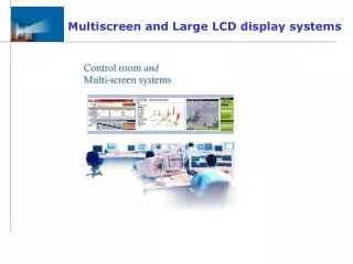
Flat Panel Display • Flat panel displays, or flat screens, are used for systems that have limited space. • 2 Widely Used Types • Liquid Crystal Displays (LCDs) • Light-emitting Diodes (LEDs) • Applications • Laptop computers • Calculators • Hand-held organizers • Digital clocks • VCR/Stereo displays • And so on... Chester F. Carlson Center for Imaging Science
Liquid Crystal Display • What is a liquid crystal? • A material that exists between the liquid and solid phases of matter. • When an electric field is applied to a liquid crystal the optical properties of the matter change. • Causes light to passes through at varying brightness levels. Chester F. Carlson Center for Imaging Science
Liquid Crystal Display Direction of polarization • Liquid crystals are flattened between two glass plates. • The crystal layer is a few microns thick. • A transparent electrical conductor is placed on the inner sides of the glass. Liquid Crystal Layer • Perpendicularly oriented polarizers are placed over the outer sides of each glass plate Conductor Glass Layer Polarizer Liquid Crystal Device Chester F. Carlson Center for Imaging Science
Liquid Crystal Display • How does it work? • When the voltage is off: • The liquid crystals are in a relaxed state and therefore they are aligned (i.e., arranged parallel to one another). • Polarized light that has passed through the first polarizer is unaffected by the aligned crystals and is blocked by the second (perpendicular) polarizer. No Light Transmitted Chester F. Carlson Center for Imaging Science
Liquid Crystal Display • How does it work? • When the voltage is on: • the conductors transfer an electric field that twists the crystals • when the liquid crystals are forced to twist, so does the direction of polarization of the light • some or all of the light can pass through the second polarizer. Light Transmitted Chester F. Carlson Center for Imaging Science
Liquid Crystal Display • How does it work? • The amount of voltage controls the orientation of the crystal, or how much they will twist: • The maximum amount of light is transmitted when the first and final liquid crystals are perpendicular to each other. • The minimum amount of light is transmitted when the first and final liquid crystals are parallel to each other. • Any intermediate amount of light can be transmitted when the first and final crystals are oriented at other angles. Chester F. Carlson Center for Imaging Science
Liquid Crystal Display • Screens • An individual liquid crystal device is called a cell. • A two-dimensional matrix of cells forms a screen. • Wires are connected to the cells to transfer voltages. • Certain voltages go to specific cells to control the amount of light through each cell. • Color filters are placed over each cell for color screens. • The color patterns and shapes change for different displays. • Back-lighting • The initial light source needs to be bright enough to pass through the LCD cells and be detected by a viewer’s eye. Chester F. Carlson Center for Imaging Science