Download
1 / 29
290 likes | 471 Views
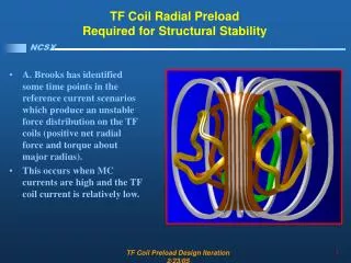
Vertical Stability Coil Structural Analyses. P. Titus, July 27 2010. Criteria for IV Coils Will be Appendix D of the In-Vessel Component Criteria. Copper:. This will be Fatigue Driven. Primary Loads are Supported by the Case, Thermal Stresses are Self Relieving

E N D
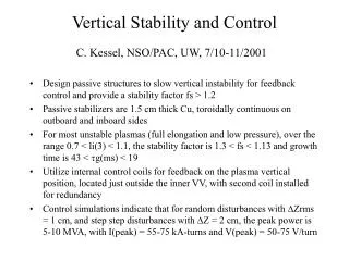
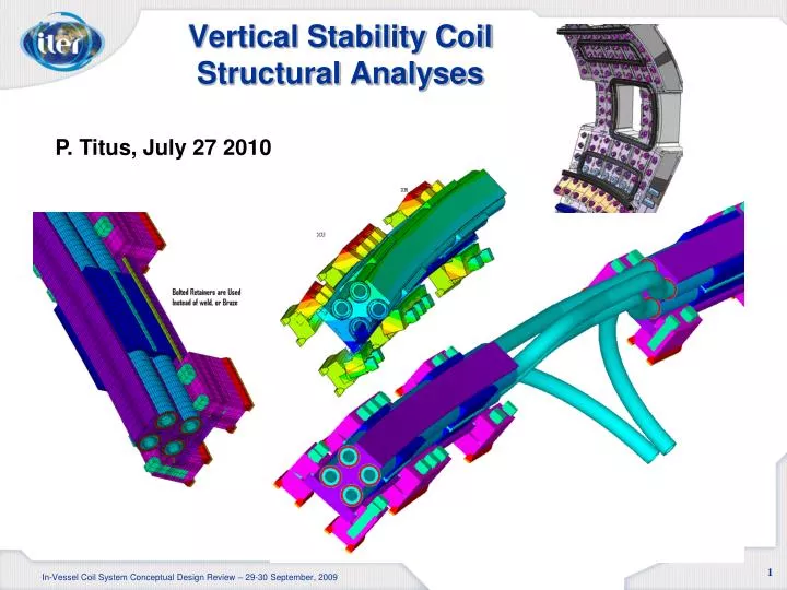
Vertical Stability Coil Structural Analyses P. Titus, July 27 2010 In-Vessel Coil System Conceptual Design Review – 29-30 September, 2009
Criteria for IV Coils Will be Appendix D of the In-Vessel Component Criteria Copper: This will be Fatigue Driven. Primary Loads are Supported by the Case, Thermal Stresses are Self Relieving Failure is Leak Due to Crack Propagation Stainless Steel: Also Fatigue Driven, but Must Support Primary Loads 2 In-Vessel Coil System Conceptual Design Review – 29-30 September, 2009
Joule Heating Loads (M. Mardenfeld Early Results) (257.2-212)* 5/9 =25.1 deg C Latest results are the same or less than 25deg C except the double turn failure results. Charlie’s Design Point is now 20 deg 3 In-Vessel Coil System Conceptual Design Review – 29-30 September, 2009
Structural Model Features Model is a 10 degree cyclic symmetry model Coils are supported every 5 degrees with Clamps Temperatures modeling the Joule heat and nuclear heat Based on Nuclear Heat from Russ Feder Radial forces are computed from SQRT(1.2) MN/40 degree sector. Vertical forces are computed from SQRT(1.2) MN/40 degree sector Radial and Vertical Forces are applied concurrently Sliding gap-friction is modeled between Spine, Sheath, MgO and conductor. A Retainer Clamp is Used Rather than Weld or Braze. 4 In-Vessel Coil System Conceptual Design Review – 29-30 September, 2009
Present Design Iteration Mesh Generation “Feet” Modeling Welds and Vessel Connection The 2D model is swept through 10 degrees. Then regions between clamps and bolts are deleted to form the model. 5 5 In-Vessel Coil System Conceptual Design Review – 29-30 September, 2009 In-Vessel Coil System Conceptual Design Review – 29-30 September, 2009
Gap Elements between all MgO conductor Components VS Structural Model Gap Elements at Clamps Displacement Constraints Model Cyclic Symmetry SST “Spine” 6 In-Vessel Coil System Conceptual Design Review – 29-30 September, 2009
Temperature from Joule Heat/Water Cooling input as a Boundary Condition In-Vessel Coil System Pre-Preliminary Design Review – 26-27 July 2010
Nuclear Heat taken from Russ Feder’s Calculation Temperatures are calculated from a Steady State Heat Conduction Analysis 8 In-Vessel Coil System Conceptual Design Review – 29-30 September, 2009
Modeling Nuclear Heat In-Vessel Coil System Pre-Preliminary Design Review – 26-27 July 2010
Electromagnetic Loads VSFORCE= 1.1526e6**.5 Some Analyses Still Use the Previous 2 MN in Each Direction In-Vessel Coil System Pre-Preliminary Design Review – 26-27 July 2010
Disruption Inductively Driven Electromagnetic Loads Around the upper VS ELM the vessel current density is 10 amps per mm^2 with the case If the current density is the same in the case as in the vessel, The case currents are as high as 10*20231=202kA Currents are comparable to Nominal 240kA currents – Thus forces are. 11 In-Vessel Coil System Conceptual Design Review – 29-30 September, 2009
1.2e6 N per 40 degree sector Vector Sum of Radial and Vertical Directions are used /solu bfe,all,temp,1,380 !100C esel,real,11,14 $nelem bfe,all,temp,1,400 ! Conductors 20C hotter Nall $eall Solve $save /title, Disruption + Normal Operating Loads 2e6/40deg esel,mat,1 $nelem f,all,fz,vsforce/4/46656 ! there are 29160 nodes in the conductors and 2e6 is for 40 degrees f,all,fx,-vsforce/4/46656 Nall $eall Solve $save /title, Disruption + Normal Operating Loads +Nuclear ldread,temp,last,,,,therm,rth Nall $eall Solve $save /title, Lorentz+Shared Ves Disrup Current + Normal Operating Loads 2*2e6/40deg esel,mat,2 $nelem f,all,fz,2*vsforce/4/52486 f,all,fx,-2*vsforce/4/52586 Nall $eall Solve $save Fini $/exit LDREAD Temps from Nuclear Radiation Thermal Analysis An additional 1.2e6 N Vector Sum of Radial and Vertical Directions are applied on the case to simulate loads from shared vessel currents 12 In-Vessel Coil System Conceptual Design Review – 29-30 September, 2009
M25 Bolts – Bolt Preload + Joule Heat Load Step ~100 MPa Bolt Preload ~400 MPa Preload Eliminated Clamp Lift-Off In-Vessel Coil System Conceptual Design Review – 29-30 September, 2009
CDR Model Response, No Shared Vessel Currents In-Vessel Coil System Conceptual Design Review – 29-30 September, 2009
CDR Model Response, With Shared Vessel Currents In-Vessel Coil System Conceptual Design Review – 29-30 September, 2009
PDR Model Response, With Shared Vessel CurrentsLower Bolt Preload is Required In-Vessel Coil System Pre-Preliminary Design Review – 26-27 July 2010
With the Full Current Inventory (1.2MN/40deg) in Conductors and Spine, Stresses in the Spine are Acceptable In-Vessel Coil System Conceptual Design Review – 29-30 September, 2009
Conductor Stresses-Will be qualified by fatigue analysis Conductor Stress With Joule Heat In-Vessel Coil System Conceptual Design Review – 29-30 September, 2009
Conductor Stresses-Will be qualified by fatigue analysis These Results are for the CDR 2MN Loading in Each Direction Conductor Stress With Joule Heat and Normal Operating Lorentz Loads Tensile Stresses are Low In-Vessel Coil System Conceptual Design Review – 29-30 September, 2009
Weld Stresses at the Clamp BodyCDR Design at 2MN – Design Similar to PDR Design The peak weld stress of ~70 MPa tension is modest. It will provide some headroom for fatigue evaluations. In-Vessel Coil System Conceptual Design Review – 29-30 September, 2009
Weld Stresses CDR Design at 2MN – Design Similar to PDR Loads Per 10 Degree Model Section, Summed Over All All Welds LOAD STEP= 4 SUBSTEP= 1 TIME= 4.0000 LOAD CASE= 0 THE FOLLOWING X,Y,Z SOLUTIONS ARE IN THE GLOBAL COORDINATE SYSTEM FX FY FZ Radial Vertical Toroidal TOTAL VALUES 0.93804E+06 -0.10195E+07 12.464 In-Vessel Coil System Conceptual Design Review – 29-30 September, 2009
Peak Clamp to Vessel Weld Stress CDR Design at 2MN – Design Similar to PDR Peak Weld Stress Meets “Average” Static Stress Criteria In-Vessel Coil System Conceptual Design Review – 29-30 September, 2009
Mounting Bolt StressWith Adequate Preload (400 MPa), The Bolt Alternating Stress is Low. In-Vessel Coil System Conceptual Design Review – 29-30 September, 2009
Joggle Model In-Vessel Coil System Pre-Preliminary Design Review – 26-27 July 2010
Only Copper is Modeled Only Toroidal Field is Applied Fixity is assumed where the conductor enters the splines Turns need to be shortened to Reduce the length that crosses the toroidal field In-Vessel Coil System Pre-Preliminary Design Review – 26-27 July 2010
VS Fault Conditions (OneD Analysis) Only Radiative Cooling, 20 Minute Cooldown Between Pulses Tube Surface Temp Radiating to 373K, Tube emissivity =.3, Vessel emissivity =.8, Nuclear Heat = 1.4MW/m^3, Tube Thickness = 1.9mm 500 sec 650 K 875K 1000 sec 1050K 1500 sec Stresses Due to These TBD In-Vessel Coil System Conceptual Design Review – 29-30 September, 2009
Conclusions The VS coil conceptual design is In a comfortable design space to finish preliminary and go forward final design Conductor thermal stresses are low because of the axisymmetry of the winding (no corner bends as in the ELM). Lead break-outs will have to preserve this feature Case stresses are high under the clamp details but with some slight modifications, these will meet static and fatigue allowables. Bolt stresses during the disruption are within the allowables of high strength bolts. Preloading the bolts eliminates the alternating component. Assuming shared vessel currents during the disruption, may be overly conservative. Should current density be halved? Does Proximity to the ELM Coils Still Make the Clamp Bolting Challenging – Investigate Common ELM/VS Clamps? 27 In-Vessel Coil System Conceptual Design Review – 29-30 September, 2009
VS Issues and Resolution Plan ITER IVC IDR 26-28 July 2010
Clamp Bolt Stress Comparable to FEA Results 29 In-Vessel Coil System Conceptual Design Review – 29-30 September, 2009