Download
1 / 13
130 likes | 236 Views
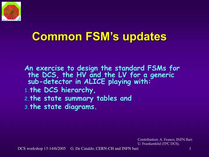
Common FSM’s updates. An exercise to design the standard FSMs for the DCS, the HV and the LV for a generic sub-detector in ALICE playing with: the DCS hierarchy, the state summary tables and the state diagrams. Contribution: A. Franco, INFN Bari U. Frankenfeld (TPC DCS) ,. SBD DCS.

E N D
Common FSM’s updates An exercise to design the standard FSMs for the DCS, the HV and the LV for a generic sub-detector in ALICE playing with: the DCS hierarchy, the state summary tables and the state diagrams. Contribution: A. Franco, INFN Bari U. Frankenfeld (TPC DCS), G. De Cataldo, CERN-CH and INFN bari
SBD DCS CF DB An example of sub-detector DCS hierarchy for the exercise Work in progress SMI Control Unit Testing SMI Device Unit Hardware Device HV BEAM? LV/FEE COOL GAS Phis. Param. LCS CONFIG SCRIPT INTERF. LVPS14 FEEMod 1 HVMod 1 HVPS1 LVPS1 LVPS1 HV chs LV chs HV PS LV PS Cooling System GAS PLC P,T sensors PLC LCS & FSM G. De Cataldo, CERN-CH and INFN bari
The summary table for the DCS-HV states • Warnings • Keeping in mind the DCS hierarchy the table has to be read from right to left ( propagation of the STATE changing ); • The corresponding command list is reported in the followings HV state diagrams (see later); • If the cell of the empty column between DCS and HV system is white then the HV system STATE must not be propagated at the DCS level; • In case of automatic recovering the MIXED state in the HV SYSTEM resolve the HV MODULE OFF ambiguity jumping in STANDBY. MIXED is active when not all the controlled channels are in same stable state ; • In this hierarchy the HV Module can control many HV channels and the HV SYSTEM can control many HV Modules; • The state naming is not yet final (the blue NOT_READY in the yellow MIXED ? STBY_CONFIGURED in CONFIGURED?) and the table may not be exhaustive: working in progress! G. De Cataldo, CERN-CH and INFN bari
State diagram for the Detector DCS GO_STANDBY OFF GO_OFF CONFIGURE (keys) Additional diagrams: B,C,D. (see later) STANDBY GO_STANDBY CONFIGURE (key) BEAM_FILLING GO_READY DOWNLOADING STBY_CONFIGURED CONFIGURE (key) STOP GO_READY PROGRESSING_DW PROGRESSING_UP INTERMEDIATE DOWNLOADING PROGRESSING_DW_INTER PROGRESSING_ STOP BEAM_FILLING READY G. De Cataldo, CERN-CH and INFN bari
State diagram for the HV system and channel group GO_STANDBY Additional diagrams: A,B,C,D,E,F. (see later) GO_OFF CONFIGURE (keys) OFF GO_STANDBY CONFIGURE (key) GO_INTERMETIATE GO_ON STANDBY DOWNLOADING STBY_CONFIGURED CONFIGURE (key) STOP GO_ON RAMP_DOWN_LOW RAMP_UP_LOW INTERMEDIATE DOWNLOADING RAMP_DOWN RAMP_UP STOP GO_INTERMEDIATE ON G. De Cataldo, CERN-CH and INFN bari
State diagram for the single HV channel (special DU) GO_INTERMETIATE GO_ON Additional diagrams: A,B,C. (see later) OFF GO_OFF GO_ON RAMP_DOWN_LOW RAMP_UP_LOW INTERMEDIATE RAMP_DOWN RAMP_UP GO_OFF GO_INTERMEDIATE ON On the GO_ON, GO_INTERMEDIATE and GO_OFF commands the DU provides the downloading in the hardware of the corresponding set of recipes value . G. De Cataldo, CERN-CH and INFN bari
State diagram for the HV(LV) power supply Additional diagrams: A,B,C,D. (see later) Active lines on External Interlock and External disable INTERLOCK RECOVER_INTERLOCK GO_READY INTERLOCK_WENT OFF RECOVER Power Crate unsafe Conditions, Kill command GO_OFF RESET ERROR Network connection lost NO_CONTROL ON The connection between NO_CONTROL and OFF is valid if the remote control of the power supply is on also when the PS is switched off. G. De Cataldo, CERN-CH and INFN bari
The summary tables for the DCS-LV states Warnings: as for the HV table G. De Cataldo, CERN-CH and INFN bari
State diagram for the LV system and channel group Additional diagrams: A,B,C,D,E,F. (see later) GO_STANDBY GO_OFF CONFIGURE (keys) OFF GO_STANDBY CONFIGURE (key) GO_ON STANDBY DOWNLOADING STBY_CONFIGURED In order to take into account the delays in swapping the different recipes sets in the channel, the RAMP_UP and RAMP_DOWN states are needed. RAMP_DOWN RAMP_UP STOP ON G. De Cataldo, CERN-CH and INFN bari
State diagram for the single LV channel Additional diagrams: A,B,C. (see later) GO_INTERMETIATE GO_ON OFF RAMP_UP RAMP_DOWN GO_OFF GO_INTERMEDIATE ON G. De Cataldo, CERN-CH and INFN bari
WA_REPAIR The ‘ADDITIONAL diagrams ’: ERROR HANDLING (E,F in the next page!) A B C D When several modules in ER_REPAIR, or External Interlock, or power crate failure, un-calibrated board. It is the propagation of the interlock condition in HVPS1 From any state if the communication with the hardware is lost One or several tripped channels in a channel group INTERLOCK #trips ≥ Max? Yes Recovering actions Recovering actions No RECOVER RECOVER_INTERLOCK ER_REPAIR NO_CONTROL ERROR INTERLOCK_WENT When the communication is established Go to OFF Go to theappropriatestate Go to theappropriatestate Go to theappropriatestate Go to OFF • In the state diagram of the power supply the ADDITIONAL A refers to a failure of a certain number of fans or AC modules in the crate that do not prevent the HV power supply to work properly; G. De Cataldo, CERN-CH and INFN bari
The ‘ADDITIONAL diagrams II’: the COMPLEMENTARY STATE E F From any state when not all the channels or systems are in a stable state From any state when not all the channels or systems are in the same state MIXED PROGRESSING_UP (DOWN) When all the systems are in a stable state When all channels are in the same stable state Go to theappropriatestate Go to theappropriatestate G. De Cataldo, CERN-CH and INFN bari
Conclusion • For the DCS, the HV, and the LV systems the ACC is trying to provide reference FSM hierarchies along with their standard state diagrams. All the sub-detector control expert are kindly requested to verify if these state diagrams fits with the sub-detector operation and give feedback to the ACC. • In order to integrate in the DCS any different system with a synchronized FSM, each control expert could do the same exercise: • Starting from the system operation design the corresponding FSM hierarchy using the Device and Control Unit (SMI++ object that can be implemented in the PVSS FW); • Starting from the DU interfacing the hardware, try to synchronize the state list up to the DCS level using the state summary table; • Draw the corresponding state diagram with a detailed command list. • For any question please do not hesitate to contact me G. De Cataldo, CERN-CH and INFN bari