Download

1 / 17
170 likes | 236 Views
Learn about digital logic gates (AND, OR, NOT) and their operations through examples, truth tables, and applications in computer programming. Discover how to manipulate binary numbers using logic gates.

E N D
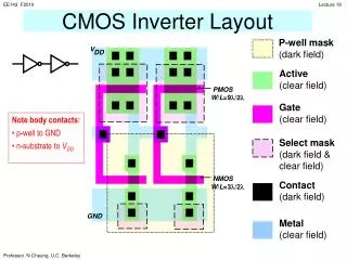
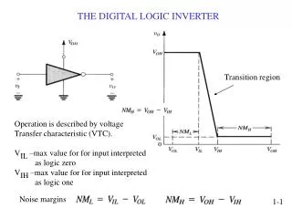
The NOT operation (complement) is shown with an overbar. Thus, the Boolean expression for an inverter is X =A. A X The Inverter The inverter performs the Boolean NOT operation. When the input is LOW, the output is HIGH; when the input is HIGH, the output is LOW. LOW (0) HIGH (1) HIGH (1) LOW(0)
A X The Inverter Example waveforms: A X A group of inverters can be used to form the 1’s complement of a binary number: Binary number 1 0 0 0 1 1 0 1 0 1 1 1 0 0 1 0 1’s complement
A A X X The AND Gate B B The AND gate produces a HIGH output when all inputs are HIGH; otherwise, the output is LOW. For a 2-input gate, the truth table is 0 0 0 1 1 0 1 1 0 0 0 1 The AND operation is usually shown with a dot between the variables but it may be implied (no dot). Thus, the AND operation is written as X = A .B or X = AB.
A A X X The AND Gate B B Example waveforms: The AND operation is used in computer programming as a selective mask. If you want to retain certain bits of a binary number but reset the other bits to 0, you could set a mask with 1’s in the position of the retained bits. If the binary number 10100011 is ANDed with the mask 00001111, what is the result? Example Solution 00000011
A X A X The OR Gate B B The OR gate produces a HIGH output if any input is HIGH; if all inputs are LOW, the output is LOW. For a 2-input gate, the truth table is 0 0 0 1 1 0 1 1 0 1 1 1 The OR operation is shown with a plus sign (+) between the variables. Thus, the OR operation is written as X = A + B.
A X A X The OR Gate B B The OR operation can be used in computer programming to set certain bits of a binary number to 1. ASCII letters have a 1 in the bit 5 position for lower case letters and a 0 in this position for capitals. (Bit positions are numbered from right to left starting with 0.) What will be the result if you OR an ASCII letter with the 8-bit mask 00100000? Example Solution The resulting letter will be lower case.
The NAND operation is shown with a dot between the variables and an overbar covering them. Thus, the NAND operation is written as X = A .B (Alternatively, X = AB.) A A X X The NAND Gate B B The NAND gate produces a LOW output when all inputs are HIGH; otherwise, the output is HIGH. For a 2-input gate, the truth table is 0 0 0 1 1 0 1 1 1 1 1 0
The NOR operation is shown with a plus sign (+) between the variables and an overbar covering them. Thus, the NOR operation is written as X = A + B. A X A X The NOR Gate B B The NOR gate produces a LOW output if any input is HIGH; if all inputs are HIGH, the output is LOW. For a 2-input gate, the truth table is 0 0 0 1 1 0 1 1 1 0 0 0
A X A X The NOR Gate B B The NOR operation will produce a LOW if any input is HIGH. Example When is the LED is ON for the circuit shown? Solution The LED will be on when any of the four inputs are HIGH.
The XOR operation is written as X = AB + AB. Alternatively, it can be written with a circled plus sign between the variables as X = A + B. A X A X The XOR Gate B B The XOR gate produces a HIGH output only when both inputs are at opposite logic levels. The truth table is 0 0 0 1 1 0 1 1 0 1 1 0
A X A X The XOR Gate B B Notice that the XOR gate will produce a HIGH only when exactly one input is HIGH. Question If the A and B waveforms are both inverted for the above waveforms, how is the output affected? Solution There is no change in the output.
Additional Logic Operations – XNOR • Exclusive NOR is the complement of the XOR operation • Alternatively the output is 1 when modulo 2 input sum is not equal to 1
Minimal Logic Operator Sets • Minimal Logic Operator Sets • - AND , OR, NOT are all that’s needed to express any combinational logic • - Two other minimal logic operator sets exist • Just NAND gates • Just NOR gates • - We can demonstrate how just NANDs or NORs can do AND, OR, NOT • Operations • NAND as a Minimal Set
Fixed Function Logic Some common gate configurations are shown.
Fixed Function Logic Logic symbols show the gates and associated pin numbers.
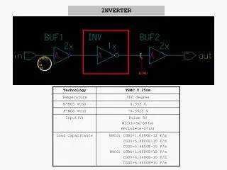
Fixed Function Logic Data sheets include limits and conditions set by the manufacturer as well as DC and AC characteristics. For example, some maximum ratings for a 74HC00A are: