Download
1 / 17
180 likes | 302 Views
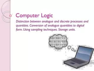
Computer Logic. Analogue & Digital Data. Analogue. An analogue/continuous devise is one which data is represented by some quantity which is continuously changing. In analogue data any value can be represented because the quantity can take any value in the range used. Examples of analogue data:

E N D
Analogue & Digital Data. • Analogue. • An analogue/continuous devise is one which data is represented by some quantity which is continuously changing. In analogue data any value can be represented because the quantity can take any value in the range used. • Examples of analogue data: • Watches, where hands move round a dial. The time is represented by the positions of the hands on the dial. • A dimmer switch. • An electric motor.
Discrete/Digital data. • Lets take a water tap. Since small drops are falling one at a time we can count the number of drops falling per minute.Data that is found by a set of pulses and can be counted is called discrete/digital data. This can take one of fixed number of states. • Examples of digital data: • The display of the calculator is the digital with the numbers in decimal. Each can have any of ten separate states:0,1,2,3,4,5,6,7,8,9. This makes it clear that the calculator can display 10 varieties when it comes to characters. • A switch can be on or off.
Multiple Stable states Multiple stable states are electronic devices that can be more than two states. Electronic devices which have multiple stable states are difficult to produce cheaply and reliably. Bi-Stable States. Bi-stable states are electronic devices which can be in one of two states. We think of these bi-stable states as being On and Off states (the device can be an electronic switch). These two states can represent anything which can take one of two possible values, such as voltage or the binary digits/bits O and 1.
Convert Analogue to Digital. An analogue-to-digital converter is an inter face to convert an analogue signal to a digital one. This conversion is sometimes called demodulation. Analogue Signal Digital Signals Controlled Device Processor A-D Converter
Convert Digital to Analogue. A digital-to-analogue(D-A) converter is an interface to convert a digital signal to an analogue one. It converts a set of binary signals to one single varying voltage. Digital Control Signals Analogue Signal Controlled Device Processor D-A converter
True False * * Binary Numbers. A digital signal can be 1 out of 2 possible states. This is signal is called BIT (binary digit). A bit can be represent One of Two possible values. Using just one bit, we can represent any data that can only have 2 possible states. E.g. 1 and 0, True and False, Male or Female, On or Off. Male or Female 1 or 0 True or False Table
Definition: Binary/Bit~a 1 or a 0 used to represent data. The term is also uses for the smallest unit of storage,which just stores a 1 or 0. The units of storage is the Bit.
Using 2 bits. Lets say we would like to represent the seasons: there are 4 seasons so how could we represent with one bit? We have to use 2 bits. The bit on the left is the most significant while the bit on the right is the least significant. Two bits gives us 4 possible patterns that is 4 seasons. The seasons are in digital form. Inside the computer they will be as binary form. Most Significant Bit Least Significant Bit Meaning 0 0 Summer 0 1 Spring 1 0 Autumn 1 1 Winter
Bulb 1 Bulb 2 Bulb3 0 0 0 0 0 1 0 1 0 0 1 1 1 0 0 1 0 1 1 1 0 1 1 1 To represent the days of the week 2 bits aren’t enough. So we have to use more than 2 bits we use 3 bits. With 3 bits we can represent 8 values. Example: Consider 3 bulbs: use 1 to represent On and 0 will represent Off. 6512385871239 is a decimal and the most significant is the 6 and the least significant is the 9
Total number of variations that can be represented in a number of bits can be found using the formula 2n The range of numbers that can be presented is represented by 0...2n - 1
Truth tables. A truth table is a notation used in Boolean(0&1) algebra for defining the output of a logic gate for all possible combinations of inputs. By looking at a truth table, one is able to know the output of any possible combination of inputs. Logic Gates. A logic gate is a hardware item that has one or more input and one output. Logic gates work with binary numbers, therefore the output must always be a 1 or a 0. The output of a logic gate depends on the input of the gate. Or gate And Gate Not Gate
Situation: A parent tells her son that if he gets a 3 marks more than 80 in his annuals exams, and comes home early from his grad party she will get him digital cable for the summer. Which gate? Write the truth table and represent it in a gate. Uses 1 & O to represent. Gate:AND. 3 marks:80+ Come home early Digital Cable? 0 0 0 0 1 0 1 0 0 1 1 1
When the input is: (0,0),(0,1),(1,0) the output is always 0. In this case if the switch represents the numbers, the bulb is off in this situation. When the input is: (1,1) the output is 1. In this case the bulb is on because the switches represent 1 and 1
Harry Potter 1 Harry Potter 2 Harry Potter 3? 0 0 0 0 1 1 1 0 1 1 1 1 Situation: A parent tells her son that if he reads Harry Potter Book1 or Harry Potter book 2, she’ll buy him the 3rd one. Which gate? Write the truth table and represent it in a gate. Uses 1 & O to represent. Gate :OR.
If the input is: (0,0). The output will be 0. In this situation the bulb will be off. The switches represent the numbers. If the input is: (0,1),(1,0)or(1,1). The output is 1. In this case the bulb will be turned on.
True False 0 1 1 0 This is a not gate. Situation: A teacher corrects exam papers. If a student passes he needn’t do the revision homework but if he doesn’t pass he must do it. Which gate? Write the truth table and represent it in a gate. Uses 1 & O to represent. Gate: NOT.