Download
1 / 58
710 likes | 1.17k Views
5. Compressor. Introduction. In the seventeenth century it was discovered that air had weight and was compressible. Its practical use in a compressed form started at that time.

E N D
Introduction • In the seventeenth century it was discovered that air had weight and was compressible. Its practical use in a compressed form started at that time. • Early documented used of compressed air was for the reed type of musical wind instrument, which later became the pipe organ. • The first compressor constructed in the United States was in 1865.
Theory of Gas Compression • Air has weight and it is the weight of the column of air over a particular location that determines the atmospheric pressure at that particular location. • At sea level and under average temperature and moisture conditions, a one square inch column of air extending up to the uppermost limit of the atmosphere weighs about 14.7 pounds. • Atmospheric pressure at sea level is, therefore, about 14.7 pounds per square inch at 60oF and 36% relative humidity.
Theory of Gas Compression • Consider a confined volume of gas. The gas molecules are distributed throughout the volume and are widely separated as compared to their size. • They move at high velocity and collide frequently with each other and with the walls of the vessel. • The continuous bombardment of the enclosing walls produces pressure and the intensity of pressure depends on the number, mass, and velocity of the molecules. • Temperature is a measure of the kinetic energy of the molecules which, in turn, depends on their mass and velocity. • If the confined gas is heated, its stored energy will be increased and the molecules will move with increased speed. • Therefore both pressure and temperature will increase. • The rise in temperature is evidence of an increase in the amount of internal energy stored in the gas.
Theory of Gas Compression • If the enclosing vessel is fitted with a piston so that the air can be compressed into smaller volume, the moving piston delivers energy to the molecules, causing them to move with increased velocity. • As with heating, this results in a temperature increase. Thus, the work of compression is stored as internal energy in the air. • Further more, all of the molecules have been forced into smaller space which results in an increased number of collisions on a unit area of the wall. This, together with increased molecule velocity, results in increased pressure. • Compression may be thought of as forcing a confined volume (or weight) of gas into a smaller space to increase pressure, • It is accompanied by a rise in temperature (and an increase of stored internal energy).
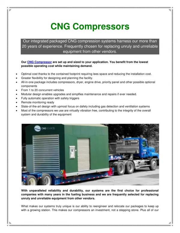
Purpose of Gas Compressor Purpose of gas compressor is to compress a gas from an initial or suction pressure to a final or higher discharge pressure. Compression of gases to adequate higher pressure is necessary to perform operational functions. • Transmission – move gas from place to place or from one part of a process operation to another. • Recovery – mixture of gases remaining after separating condensable component are compressed for further liquification. • Air compression - conveying, for power tools, process operations, etc. .
How Compressors Works • Individual gas always travel at high speed, at normal temperature, they strike against the walls of an enclosing vessel and produce what is known as pressure. • When heat is added, the molecules even travel faster, so they hit the containing walls of the vessel harder and more often. This shows up as greater pressure. • If the enclosing vessel is fitted with a piston so that the gas can be squeezed into a smaller space, molecule travel is restricted. The molecules hit the walls with greater frequency increasing the pressure. The moving piston also delivers energy to the molecules, causing them to move with increased velocity. • As with heating, this results in temperature increase. Furthermore, all the molecules have been forced into a smaller space, which results in an increased number of collisions on a unit area of wall. This , together with increased molecules velocity results in increased pressure.
How Compressors Work • The compression of gases to higher pressure can result in very high temperature creating problems in compressor design. • All basic compressor elements, regardless of type, have certain limiting operating conditions. • Basic elements are single stage. • When a temperature limitation is involved it becomes necessary to multiple stage the compression process.
Major Design Classification There are 2 major design classification of compressor: • Positive displacement • Dynamic
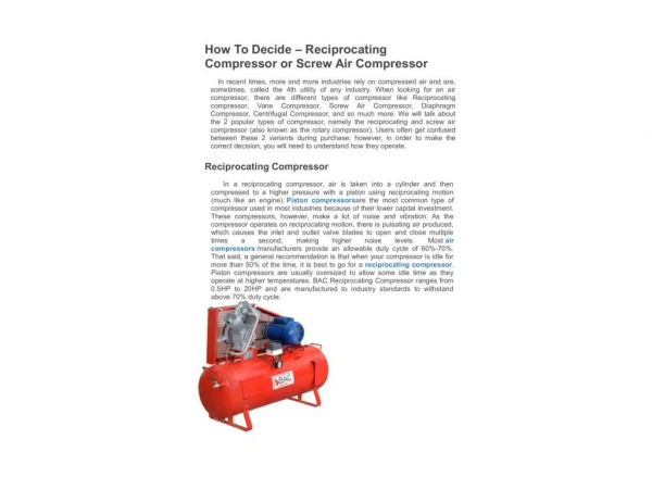
1. Positive Displacement Compressors In positive displacement compressor, successive volumes of air are confined within a closed space and pressure is increased by reducing volume of space Two types of positive displacement compressors: • Reciprocating • Rotary
Positive Displacement Compressors 1. Reciprocating
Reciprocating Compressor-principal elements The principal elements of a reciprocating gas compressor are: • Cylinder, heads, pistons, inlet and discharge valves • Power-transmitting parts such as crankshaft, crossheads, connecting rods, flywheel • Lubricating system.
Reciprocating Compressor Reciprocating compressor uses automatic spring loaded valves which open only when the proper differential pressure exist across the valve. Operations 1. Inlet valves open drawing in gas when the pressure in the cylinder is slightly below the intake pressure 2. During the compression stroke the inlet and discharge valves are closed until the pressure in the cylinder is slightly above the discharge pressure 3. The discharge valves open and the gases flow out until the discharge stroke is completed • As the piston moves back in the expansion stroke both the inlet and discharge valves remain closed • The gases trapped in the clearance space increase in volume causing a reduction in pressure • When the pressure in the cylinder once again is slightly below the inlet pressure the inlet valves open drawing in gas and the compression cycle is repeated.
Positive Displacement Compressor • Rotary Compressor • In rotary compressors, force is given to the gas or air by a rotating impeller. • Design of rotary compressors are numerous and there are many modifications of the rotary principle • Generally one-stage machines, compressing to moderate pressures. • Most of these units have no provision for cooling water. • In some machines, it is necessary to have the rotary elements – cams, drums, blades or gears – form an airtight contact with the casing so that the air can not leak neither around the ends of the rotary member nor past the peripheral surface. • Volume of air increases with speed • Lubrication consist of supplying a film of oil to the surface of all sliding internal parts and to the bearing supporting the rotary parts. Purpose is to prevent wear and abrasion of part in contact and as sealing film to prevent air leakage.
Rotary Compressor Sliding vane Rotary Compressor
Rotary Compressor Two Impeller Rotary Compressor
Rotary Compressor Screw Type Rotary Compressor
2. Dynamic Compressors Dynamics compressors use rotating elements to accelerate the gas by diffusing action, velocity is converted to static pressure. Total energy in A flowing gas stream is constant. Entering an enlarged section, flow speed is reduced and some of the velocity energy turns into pressure energy. Thus, static pressure is higher in the enlarged section. Two types of dynamic compressors: • Centrifugal • axial
Dynamic Compressors - Centrifugal Centrifugal compressor is a dynamic displacement machine wherein inertial forces is applied to a gas transmitted by an imeller which, by dynamic centrifugal forces is applied to the gas transmitted by an impeller which, by dynamic centrifugal motion, adds velocity energy through acceleration of the gas. This velocity energy (called kinetic energy) is retarded in a vaned or vaneless diffuser, transforming most of that velocity energy into additional static pressure. In the diffuser, the same as in the additional compressor components, like the inlet collector, exit collector, stationary vanes to guide the flow, etc, there are pressure losses. Therefore, the impeller has to produce enough energy to satisfy the pressure requirements plus those losses.
Dynamic Compressors - Centrifugal • Centrifugal compressors or blowers consist of a casing in which revolve one or more impellers (bladed wheels) mounted on a shaft supported by one or more bearings. • Gas enters the impeller near the shaft and is discharged at the outer end of the impeller blades. • When the shaft is rotated, the effect of centrifugal force upon the gas within the impeller causes its compression and, at the same time, induces it to flow through the impeller. • The gas passing through the impeller is accelerated, and the increase in velocity is a form of energy convertible into additional pressure. • The conversion is produced by the gradual and orderly Deceleration of the gas either in a bladed or open diffuser, or in a volute or scroll surrounding the impeller.
Dynamic Compressors-centrifugal Centrifugal Compressor Elements • Impeller – Gas is given an outward thrust or radial velocity kinetic energy added to the gas by increasing speed • Diffusers – Reduces velocity of gas gradually converting velocity energy to pressure • Volute – Collects compressed gas and directs to outlets.
Dynamic Compressors - Centrifugal Three main types of impeller used in centrifugal compressors are: • Open Impeller • Semi-open Impeller • Enclosed Impeller
Dynamic Compressors - Centrifugal Open impeller is used in single stage compressors to produce high head with but small flow (capacity)
Dynamic Compressors - Centrifugal Semi-enclosed impeller is used in single staged compressors or in the first stage of multi-stage compressors to produce a large flow
Dynamic Compressors - Centrifugal The enclosed impeller is used in multi-stage compressors where pressure is increased in to a high discharge pressure
Operation of Centrifugal Compressor • Compression of gas is accomplished by drawing the gas into the center of the impeller and discharging it at the periphery with considerable velocity • This velocity is converted into pressure in the diffuser passage which in turn guide the gas into the inlet of the next impeller • Shaft sealing of centrifugal compressors is usually accomplished by labyrinth rings. • If the vapor being compressed is volatile or flammable, a pressure draw-off before the last ring in the compressors suction line of a liquid or gas seal on the gland to the atmosphere is frequently used.
Dynamic Compressors-Centrifugal Surge Point • There is for every speed and pressure of a centrifugal compressor a certain minimum volume below which the machine does not operate properly. This volume is called the surge point • Below it delivery of gas becomes irregular, reversing itself at frequent intervals with a characteristic noise known as surging. Surge condition N Choke condition (stone wall) head Volume Flow Compressor Performance Curve
Dynamic Compressor - Centrifugal SURGE Pressure Operating zone Surge zone B OP C A D D E Negative flow Positive flow Surge Cycle
Dynamic Compressor - Centrifugal Surge (con’t) Refer to - Surge cycle figure Consider a compressor operating in steady state at point A. If the load is reduced, the OP (operating point) must move toward B. the SURGE POINT. At B the compressor is producing more flow than the load can absorb. This fluid is temporarily stored in the discharge volume, but the discharge pressure cannot rise above B. The only relief for these conditions is for the OPERATING POINT to jump to point C. This is the flow reversal often observed during surge. With negative flow the discharge pressure drops (traject C-D). At point D we find that the flow is insufficient to build up the pressure necessary to reach B, so the OPERATING POINT jumps to E. Now the flow is in excess of the load and the OPERATING POINT will move up the curve to reach B again. This completes one SURGE CYCLE. The typical duration of one SURGE CYCLE is 0.5 to 2.0 seconds.
Dynamic Compressors - Centrifugal Surge (con’t) The consequences of surge are severe. Besides process disturbance and the eventual process trips and disruption, surge can damage the compressor: - Damage to seals and bearings is common. - Internal clearance are altered, leading to internal recycle - Lowering of compressor efficiency - Destruction of compressor rotor
Dynamic Compressors - Centrifugal Surge (con’t) Protection method As shown earlier, a combination of high discharge pressure and low flow can result in surge. Avoiding one or both of these situations prevents a compressor from going into surge. A working solution can be found in a RECYCLE or BLOW-OFF line. Operating a valve, positioned in this line, reduces the discharge pressure and increases the load thus preventing surge. Various surge control systems are not included in this general course.
Dynamic Compressors-Axial • In axial flow compressors, gas moves generally parallel to the shaft axis. • The axial compressor or blower is a dynamic type of machine, identified by the use of moving and stationary blading to accomplish the velocity-pressure conversion • for pressure increase. In general, axial compressor design is based on the theory of 50% reaction • This means that half of the pressure rise is accomplished in the rotor blade and half in the stator blade • As gas flows through the rotating blades, pressure and velocity both increase • Each row of stationary blades converts the energy of the increased velocity to additional pressure, acting as a diffuser for the gas flowing out of the preceding • row of rotating blades. Also, the stationary blades act as nozzle to guide the gas into the next row of rotating blades. • Each stage consists, therefore, of one rotating and one stationary row of blading.
Safety Devices Typical Compressor Safety Devices Name Function Relief valves - On the discharge side to relieve excessive pressure Overspeed - Trips driver when compressor exceed Shutdown predetermine safe speed Oil failure - For system fitted with pressure shutdown lubrication. Protects bearing by stopping unit when oil pressure fails Jacket-water - Shutdown compressor if water pressure fails. Valve Operated either by pressure or temperature. Over-pressure - Stops compressor when discharge pressure Shutdown goes above pre-set safe valve Excessive temp - Automatically stops unit on a pre-set high discharge Shutdown temperature Main bearing - Thermal shutdown device stops compressor if Protection bearing temperature goes too high
Over-speed safety Stop • In a typical over-speed safety stop, the revolving part is connected to the magneto drive shaft. If the engine reach a pre-set point (rpm), the weight W is thrown out, overcoming the spring S. The weight hits the plunger P which snaps down and presses the copper disk C against the contact A. This grounds the magneto and stops the engine.
Guides – How to Prevent Compressor Failure Guide: Starting of electric motor driven compressors: • If work has been done on a compressor, before starting, turn over by hand at least one revolution to make sure everything is clear • Always be sure cooling water is circulating through compressor before attempting to start. If the operator neglects to turn on the cooling water and starts the compressor first, do not turn cooling water into compressor, but shutdown and allow compressor to cool before re-starting machine • Always be sure ventilating system(s) are in operation before attempting to start • Refer to manufacturer’s instruction book for means of determining lubrication requirement • Watch any bearing that is taken up for a reasonable time to be certain it is not too tight • Never open gas cylinder without first purging it.
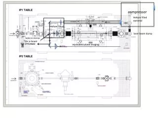
Gas Turbine Fuel Exhaust Gases Compressed air Hot gases Combustion chamber HPT Compressor LPT Load Air in Flow Diagram of a Simple Cycle 2 Shaft Gas Turbine
Gas Turbine Gas turbine Principle of Gas Turbine operation The gas turbine portion of the mechanical drive gas turbine unit is that part in which fuel and air are used to produce shaft horsepower. The compressor/high pressure turbine rotor is initially brought to 20% speed by a starting device. Atmospheric air drawn into the compressor is piped to the combustion chambers where fuel is delivered under pressure. A high voltage spark ignites the fuel-air mixture. [Once ignited, combustion will remain continuous in the air stream for as long as fuel is delivered to the combustion chamber]. The hot gases increase the speed of the compressor/high pressure turbine (HPT) rotor. This in turn increases the compressor discharge pressure.
Gas Turbine Gas turbine Principle of Gas Turbine operation (con’t) As the pressure begins to increase, the low pressure turbine rotor will begin to rotate and both turbine rotors will accelerate to operating speed. The products of combustion (high pressure/high temperature gases) expand first thru the high pressure turbine and then thru the low pressure turbine and exhausted to atmosphere. As the expanding gases pass thru the high pressure turbine amd impinge on the turbine buckets, they causes the turbine to spin; thus rotating the compressor and applying a torgue output to the driven accessories. The gases also spin the low pressure turbine before exhausting; thus rotating the load. The rotor spins in a counterclockwise direction when viewed from the inlet end.
Gas Turbine Gas turbine Principle of Gas Turbine operation (con’t) 1. Compressor section In the compressor, air is confined to the space between the rotor and stator blading where it is compressed in stages by a series of alternate rotor and stator airfoil shaped blades. The rotor blades supply the force needed to compress the air in each stage and the stators blades guide the air so that it enters the following rotor stage at the proper angle. The compressed air exists through the compressor discharge casing to the combustion chambers. Air is extracted from the compressor for turbine cooling, for bearing lube oil sealing, and for pulsation control during start up/shutdown.
Gas Turbine Gas turbine Principle of Gas Turbine operation (con’t) 2. Combustion section During operation, air from the compressor flows into the combustion wrapper and into the annular space between the liner and the flow-shied. This air flows into the liner, is mixed with fuel, and ignited. The combustion chamber has the difficult task of burning large quantities of fuel, supplied by the compressor, and releasing the heat in such a manner that the air is expanded and accelerated to give a smooth stream of uniformly heated gas at all conditions required by the turbine
Gas Turbine Gas turbine Principle of Gas Turbine operation (con’t) 2. Combustion section Combustion process Air from the engine compressor enters the combustion chamber at a high velocity, and because of this high velocity the air speed is far too high for combustion. The first thing that the chamber must do is to diffuse it, i.e. decelerate it and raise its static pressure. Because the speed of burning fuel at normal mixture ratios is not high, any fuel lit even in the diffused air stream, which now has a velocity of about 80% less, would be blown away. A region of low axial velocity has therefore to be created in the chamber, so that the flame will remain alight throughout the range of engine operating conditions.